Global Design Solutions (GDS) helps engineers, architects, facility owners, and industrial clients turn raw laser scanning data into high accuracy 3D models.
Our 3d modeling services bridge the gap between point clouds and usable CAD, BIM, and mesh deliverables. The result is faster project approvals, fewer design errors, and reliable documentation for future work.

3D Surface and Mesh Modeling
Point cloud data is often too dense or noisy to use directly. We process scans into clean surface or mesh models with precise geometry, suitable for visualization, simulation, and downstream CAD work. This laser scan modeling approach ensures that even complex features such as structural steel, piping, or curved facades are captured accurately.
We convert scanning output from plants, factories, or campus buildings into clear 3D representations. These models assist in retrofit planning, clearance verification, and clash detection, giving project teams confidence before construction begins.
For projects that demand parametric design, we convert scan data into scan to cad model formats. Features such as tanks, conveyors, holes, and pipe networks are modeled to industry standards, making them ready for direct use in design software. This saves engineering teams from manual redrawing and reduces project turnaround times.
Our as built 3d model services link scan-derived geometry to BIM environments. We create models that integrate into Revit or similar platforms, complete with metadata and structured elements. This enables architects, contractors, and facility managers to coordinate efficiently, manage assets, and plan renovations with confidence.
When existing files are missing or outdated, our reverse engineering modeling process rebuilds components and assemblies directly from scan data. The result is editable CAD models that can be used for part reproduction, equipment upgrades, or legacy system integration.
Data intake & QA – We accept common point cloud formats (.las, .e57, .rzf) and review scan quality.
Preprocessing – Noise removal, segmentation, and alignment for consistent results.
Modeling – Creation of surfaces, solids, meshes, or BIM objects to match project goals.
Quality assurance – Dimensional checks against the scan to confirm accuracy.
Delivery & support – Final models provided in CAD or BIM formats (.step, .dwg, Revit, .obj) with optional review rounds.
Models aligned within tight tolerances to source scans
Reduced field rework and change orders compared to manual measurements
Models delivered in industry-standard formats compatible with engineering workflows
Trusted by engineering firms, contractors, and facility owners requiring reliable documentation
Q1. What accuracy can you achieve from scan to model?
A1. Accuracy typically aligns within 1–3 mm, depending on scan quality and project requirements.
Q2. Can you work with scans from any equipment?
A2. Yes, we accept widely used formats such as .las, .e57, and .pts, regardless of scanner brand.
Q3. What is the typical delivery time?
A3. Small projects may be completed in days, while larger facilities or campuses may require several weeks. Timelines are confirmed during quoting.
Q4. What deliverable formats do you provide?
A4. Common formats include .step, .dwg, Revit, and .obj. Deliverables are tailored to client needs.
Q5. How do you handle complex or irregular shapes?
A5. We apply specialized modeling techniques and fitting methods to accurately capture curved pipes, irregular surfaces, and intricate structures.
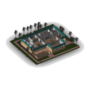
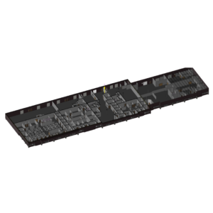
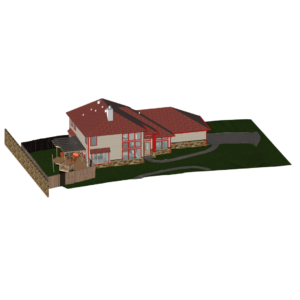
3D models are created to represent the basic geometry of the existing environment. No intelligence, no additional attributes. Models separated into model types determined by the client.
Formats provided in:
.dwg, .dxf, .rvt, and more…
Use cases:
– Measuring
– Layout review
– Asset location identification
– Tie-in and retrofit designing
– Stakeholder understanding
– And so much more…
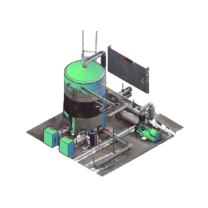
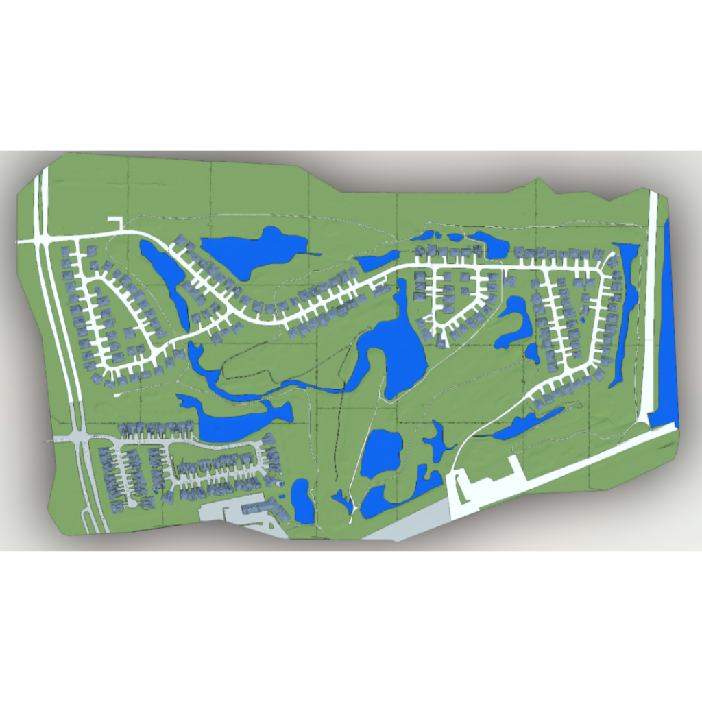
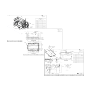
3D models are created to represent the exisiting as-builts. Attributes applied as per client requirements. Models separated into model types. Client determines LOD (Level of Detail 100-400)
Formats provided in:
.dwg, .dxf, .rvt, and more…
Use cases:
– Measuring
– Material take offs (MTO’s)
– Asset location identification
– Tie-in and retrofit design with real world attributes.
– Stakeholder understanding
– And so much more…
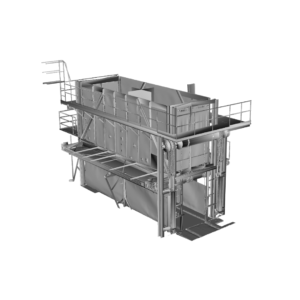
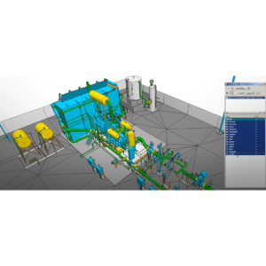
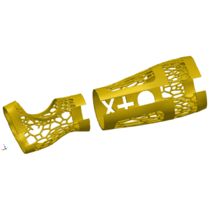
3D models are created to represent the existing as-builts with attributes applied as per client requirements. Specification catalogs determined
Software modeling in:
Revit, SPRD, PDMS, E3D, CadWorx
Use cases:
– Measuring
– Parametric models
– Tie-in and retrofit design with real world attributes.
– Engineering analysis
– Asset management
– Smart P&ID’s
-And so much more…
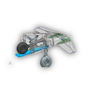
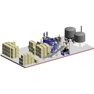
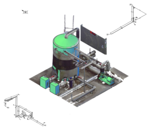
3D models are created for extreme precision. Client tolerance requirements addressed.
Formats provided in:
.slprt, .iges, .stp, .stl, .prt, native software formats also available
Use cases:
– Virtual assembly
– Modeling spines, nurbs, lofting
– Computational fluid dynamics (CFD)
– Mechanical retrofitting
– Kinematics
– Part replacement
– And so much more…
Note: All modeling can be used for Digital Twin projects.
De-construct your world
Infrastructure and strategy
From scan to fabrication
Pioneering Digital Landscapes
We build virtual products
This will close in 0 seconds
This will close in 0 seconds
This will close in 0 seconds
This will close in 0 seconds
This will close in 0 seconds
This will close in 0 seconds
This will close in 0 seconds
This will close in 0 seconds
This will close in 0 seconds
This will close in 0 seconds
This will close in 0 seconds
This will close in 0 seconds
This will close in 0 seconds