

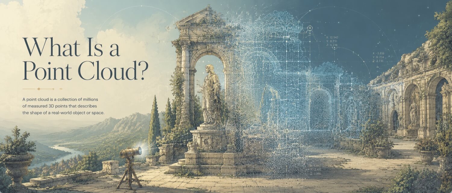
A point cloud is a three-dimensional digital coordinate model of a physical space or object. It is not a solid model, a photograph, or a mesh. It is a dense collection of individual spatial coordinates, each one representing the precise X, Y, and Z position in space where a laser pulse reflected off a physical surface.
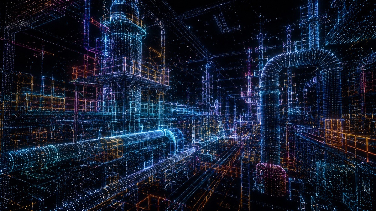
Because modern terrestrial LiDAR scanners capture millions of coordinates per second, the resulting dataset is extraordinarily dense. Viewed from a distance, the individual points resolve into what appears to be a detailed, semi-transparent digital replica of the scanned environment, often compared to a photorealistic hologram that engineers can navigate, measure, and extract data from in three dimensions.
How GDS Can Help
Most physical-to-digital projects touch more than one discipline. GDS can support the workflow from field capture through usable engineering deliverables with 3D laser scanning, 3D modeling, reverse engineering, and consulting.
GDS lists coverage across major metropolitan areas including Houston, Dallas, San Antonio, Austin, Los Angeles, San Diego, San Jose, Long Beach, Fort Worth, Irvine, Riverside, New Orleans, Baton Rouge, Shreveport, Las Vegas, and Beverly Hills. See the current GDS locations page for posted service areas.
Scope note: Specific tolerances, certification requirements, deliverables, schedules, reports, site control, and acceptance criteria should be defined in the quote, proposal, or statement of work for the individual project.
The Spatial Coordinate Model
Every point in a point cloud stores, at minimum, three values: X, Y, and Z coordinates referenced to a defined origin. Industrial-grade scanners also capture:
| Data Channel | Description |
|---|---|
| X, Y, Z | 3D spatial position in millimetres or metres |
| Intensity | Reflectance strength of the laser return (0 to 100%) |
| RGB Color | True-color imagery mapped to each coordinate |
| Timestamp | Scan capture time for time-of-flight instruments |
The intensity channel is particularly valuable in industrial environments. Dark, weathered, or rough surfaces absorb laser energy and yield low intensity values. Polished metals, reflective safety tape, and high-contrast labels return a high percentage of the signal. By rendering intensity as a grayscale gradient, GDS provides scan data in which engineers can read equipment tags, identify weld seams, and detect corrosion, even in areas captured in complete darkness.
How a Point Cloud Is Created
Terrestrial LiDAR scanners operate on the time-of-flight principle: a laser pulse is emitted, travels to the target surface, reflects, and returns to the scanner. The instrument measures the round-trip travel time with nanosecond precision and calculates the exact distance to that surface. Rotating mirror systems repeat this measurement across 360° of horizontal and 300° of vertical coverage, building a complete spherical point cloud from a single setup position in minutes.
Structured-light scanners, used for smaller industrial components and precision parts, project a patterned grid of light across the object and use stereo cameras to calculate depth from the pattern distortion, capturing surface detail at accuracies of ±0.025 mm.
Registration and Coordinate Alignment
A single scanner position cannot capture behind walls, inside pipe bends, or on the underside of equipment. To document a complete facility, the scanner is repositioned dozens or hundreds of times throughout the space. Each position produces an independent, locally referenced point cloud dataset. Combining all independent scans into a single, unified coordinate system is called registration.
Target-Based Alignment
Physical high-contrast reference targets, typically white spheres (145 mm diameter) or flat checkerboard panels, are placed throughout the environment before scanning begins. The registration software identifies these common objects across overlapping scan positions and locks adjacent scans together by matching the known geometry of the targets. This method can support tighter registration control on large facility footprints when planned correctly, but the final tolerance should be defined in the project scope.
Feature-Based (Cloud-to-Cloud) Alignment
When physical targets are not deployed, the software analyzes overlapping geometry, flat wall sections, structural steel corners, cylindrical pipe runs, and computes the spatial transformation required to align the overlapping surfaces. This targetless approach reduces field setup time but is more susceptible to error drift over long chains of scan positions.
Global Adjustment and Georeferencing
Over large-scale projects (refineries, power stations, shipyards), small registration errors accumulate across sequential scan positions. GDS engineers execute global bundle adjustment routines that minimize total registration error across all scan positions simultaneously, then tie the unified point cloud to a georeferenced survey control network (tied to state plane coordinates or site datums). This ensures that point cloud coordinates match real-world survey benchmarks and that clash detection models are spatially correct when overlaid on civil drawings.
What Does a Point Cloud Contain?
A registered, quality-controlled point cloud delivered by GDS contains:
- Full spatial coordinates for all scanned surfaces within the project boundary
- Intensity-mapped grayscale for equipment identification and condition assessment
- Registered true-color imagery (when color scanning is specified) for photorealistic visualization
- Metadata including scanner serial number, calibration records, scan date/time, and GPS tie-in information
Common delivery formats include .e57 for neutral point-cloud exchange, .rcp/.rcs for Autodesk workflows, and .las/.laz for GIS and civil workflows. The final format should be confirmed based on the client software and downstream use.
From Point Cloud to Engineering Deliverable
A raw point cloud is the starting material for every downstream digital engineering deliverable. Its role in the production chain:
| Downstream Use | What Happens to the Point Cloud |
|---|---|
| Facility BIM model | Imported as spatial underlay; engineers trace over it in Revit or AutoCAD |
| Reverse engineering | Meshed into polygon surface; CAD engineer rebuilds parametric solid over mesh |
| Clash detection | Loaded into Navisworks alongside design model; spatial conflicts identified |
| As-built documentation | Registered cloud delivered as the record document |
| Deviation analysis | Cloud aligned to nominal CAD; GOM Inspect or PolyWorks calculates deviations |
Quick Facts
Continue Reading
The next best article depends on where you are in the project. These suggested reads connect this topic to the next practical decision your team is likely to face.
FAQ
How big is a typical point cloud file?
File size varies with scan density and project scale. A single interior room scan position typically produces 200 to 500 MB in .e57 format. A full industrial facility with 100 to 300 scan positions commonly generates datasets of 100 GB to 1 TB before compression. LAZ compression reduces LAS file sizes by 80 to 90%.
What software can open a point cloud file?
Common point cloud viewers include Autodesk ReCap (free), Leica Cyclone TruView (free web viewer), and CloudCompare (open source). CAD and BIM platforms including Autodesk Revit, AutoCAD, Navisworks, and Bentley MicroStation import point clouds natively. For metrology and inspection, PolyWorks and GOM Inspect are industry standards.
What is the difference between a point cloud and a mesh?
A point cloud is a collection of disconnected 3D coordinates with empty space between them, it has no solid surfaces. A mesh is created by connecting adjacent point cloud coordinates with triangular faces, producing a continuous, solid-looking surface skin. The mesh is the next step in converting scan data into a usable 3D model.
Can a point cloud be used for CNC machining?
Not directly. CNC CAM software requires boundary-representation (B-Rep) solid models with mathematically defined surfaces. A point cloud must first be converted to a mesh, and then reverse-engineered into a parametric STEP or Parasolid file before it can be used to generate CNC toolpaths.
Need a Registered Point Cloud for Your Facility?
GDS delivers fully registered, quality-controlled point cloud datasets in .e57, .rcp, and .las formats , ready for Revit, AutoCAD, Navisworks, and downstream BIM modeling.