

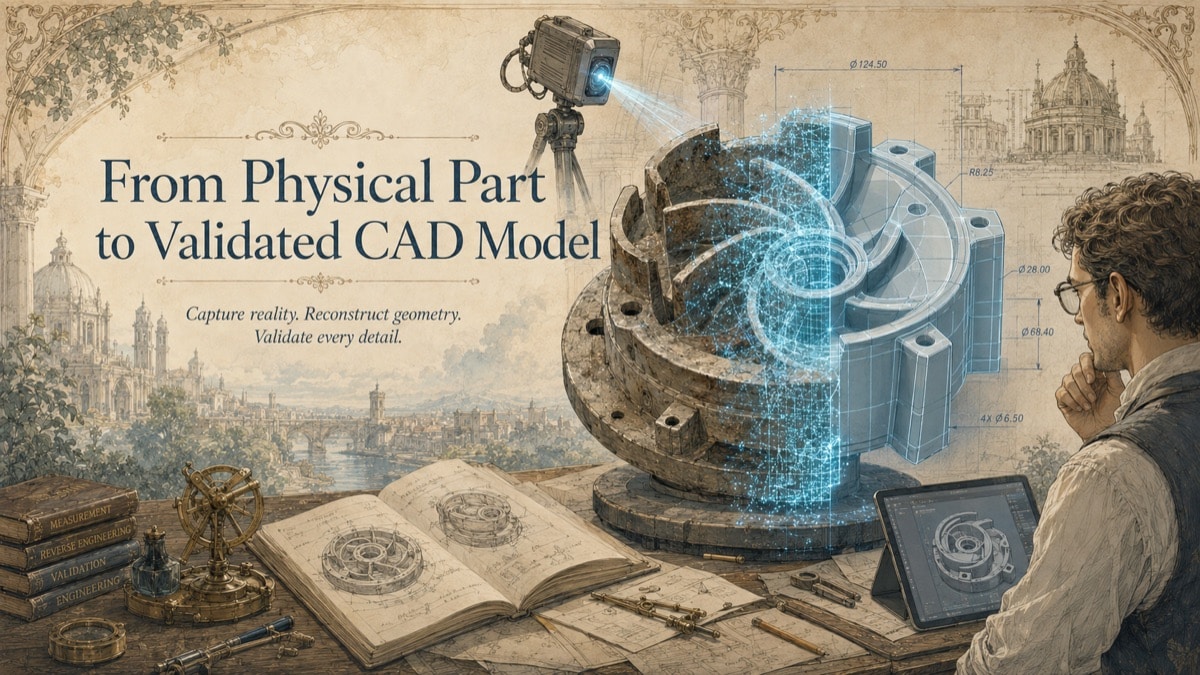
A replacement part is unavailable, the original drawings are missing, or an existing component must be modified. The physical part is the best source of geometry - but it is not a complete engineering specification by itself.
3D scanning can record accessible surface geometry efficiently. Reverse engineering then interprets that evidence into a mesh, surface model, parametric CAD model, drawing, or comparison report suited to the intended use.
The critical question is not simply, “Can it be scanned?” It is, “What must the digital result allow the client to do safely and reliably?”
What Reverse Engineering Actually Requires
Reverse engineering combines measurement with judgment. The scan may show size, shape, wear, distortion, and surface relationships. It does not automatically reveal the original nominal dimensions, manufacturing process, material specification, heat treatment, allowable tolerance, loading, or why the original designer chose a feature.
Those items may require drawings, part history, material testing, functional requirements, multiple samples, engineering analysis, or client direction. A responsible scope separates measured geometry from inferred design intent.
Choosing the Capture Method
Different assets require different measurement methods. Optical or handheld systems may suit accessible components and freeform surfaces. Portable arms, trackers, terrestrial scanners, photogrammetry, contact measurement, or other methods may be appropriate depending on size, tolerance, access, surface behavior, and environment.
GDS should confirm the available method in the project proposal rather than promise a universal accuracy by technology name. Critical bores, datums, threads, thin edges, internal passages, or reflective surfaces may need supplemental measurement or preparation.
From Scan Data to CAD
Actual-condition mesh or surface
This output follows the measured surface and may be useful for visualization, fit reference, preservation, or complex freeform geometry. It can also preserve wear and manufacturing variation that should not necessarily be reproduced.
Design-intent CAD model
A parametric model may regularize planes, cylinders, symmetry, patterns, and nominal relationships. This produces a cleaner, more editable result, but it includes engineering interpretation. Assumptions should be documented and reviewed.
Hybrid model
Many projects need design-intent features in functional areas and measured freeform geometry elsewhere. The model strategy should match the downstream use rather than forcing every part into one reconstruction method.
Validation and Critical Features
A scan-to-CAD comparison can show how the reconstructed model relates to the measured surface under a stated alignment. It does not prove that every feature is correct for manufacturing.
Critical interfaces should be identified separately. Datum strategy, mating conditions, fits, threads, seals, internal features, and tolerances may require direct measurement, multiple parts, drawings, functional testing, or responsible engineering approval.
Authorization and Intellectual Property
Before work begins, the client should confirm ownership or authorization to digitize, analyze, reproduce, or modify the item. Ownership of a physical object does not automatically resolve every patent, trade-secret, contractual, export-control, or licensing question.
GDS can request an authorization representation as part of project setup, but does not provide legal advice. Projects involving active commercial products, controlled technology, defense items, or third-party intellectual property should receive appropriate legal and compliance review.
Manufacturing Handoff
A reverse-engineered model may support quoting, redesign, tooling, CAM planning, or drawing development when those services are included. The manufacturer and responsible engineer should still review materials, tolerances, surface finish, process allowances, inspection plan, and functional requirements.
The deliverable should state whether it represents the scanned part, interpreted design intent, or a client-approved combination of both.
Interactive Project Readiness Check
Select the items your team has already defined. This planning aid does not determine technical acceptance or replace project scoping.
Quick Facts
Continue Reading
These guides connect this topic to the next practical decision your team may need to make.
Frequently Asked Questions
Can scanning determine the material of a part?
No. Scanning records geometry and sometimes color or surface appearance. Material grade and properties require records, testing, or other identification methods.
Can one worn part be used to recreate the original design?
It can provide important geometry, but wear, damage, distortion, and manufacturing variation must be identified. Multiple samples or design records may be needed to infer nominal intent.
Will the CAD model be fully parametric?
It can be when a parametric, history-based model is included in scope. STEP or surface deliverables do not automatically contain an editable feature history.
Does a deviation map certify reconstruction accuracy?
No. It documents the relationship between the model and measured data under the stated alignment, coverage, and comparison settings.
Can the model go directly to manufacturing?
It may support manufacturing, but responsible parties must still confirm materials, tolerances, fits, finishes, process allowances, and inspection requirements.
Connect this article to the right GDS workflow
GDS can help determine whether a project should begin with 3D laser scanning, 3D modeling, reverse engineering, or consulting. The correct workflow depends on the asset, intended use, required deliverable, access, and project-specific accuracy needs.
GDS provides nationwide project coverage. Current examples from the GDS locations page include Houston, Los Angeles, Irvine, and San Jose.
Ready to Define the Right Scope?
Tell GDS about the asset, decision, available records, site or part location, and intended deliverable. GDS can help identify the appropriate capture and digital workflow.