

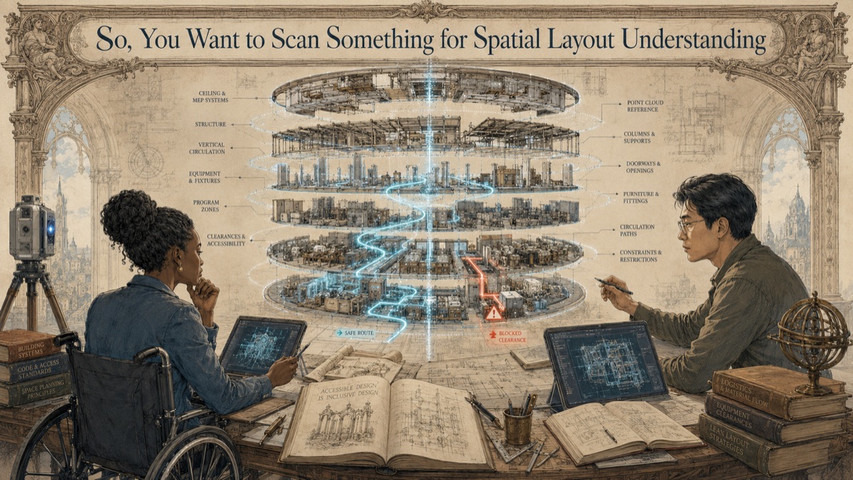
A workplace team thinks a new layout will fit because the plan says it will. The workstation count works on paper. The proposed equipment path looks clear on the PDF. The conference rooms appear to meet the planning standard. Then someone walks the site and notices the columns are wider than shown, the ceiling drops over the route, and the usable width around fixed equipment is not what the drawing suggests. The plan was technically neat, but the space was not fully understood.
Spatial layout scanning is about more than producing a floor plan. It captures the relationships that decide whether people, equipment, furniture, racking, circulation, egress, and systems can actually work together in the real environment. GDS can use 3D laser scanning to create a measured baseline for visible geometry, then convert that baseline into planning drawings, ceiling maps, clearance diagrams, area studies, or scan-derived models.
Key Takeaway
Spatial planning requires more than a floor plan. A coordinated scan can document usable area, height, columns, clearances, equipment, and access routes so planners can evaluate the real three-dimensional constraints of the space.
The Problem With Planning From Flat Drawings
This is why GDS treats scanning as a decision-support workflow, not just a technical field activity. The question is not simply, "Can we scan it?" The more useful question is, "What decision must the data support, and what evidence will make that decision safer?"
What Spatial Understanding Actually Means
A room dimension is not the same as spatial understanding. Space planning depends on clearances, height, access, circulation, fixed obstructions, structure, equipment envelopes, exits, loading paths, and adjacencies. A scan gives the team a way to measure those relationships rather than estimate them.
This matters when the project depends on usable space instead of gross space. The drawing may show a large open area, but columns, low beams, equipment, service drops, or code-driven clearances can materially change what the area can support.
The Five-Phase Layout Intelligence Pipeline
Phase 1 - Define the planning decision
Clarify whether the team needs area calculations, furniture planning, racking feasibility, circulation review, equipment movement, leasing data, or design context.
Phase 2 - Capture the spatial envelope
Scan the floors, walls, columns, soffits, ceiling conditions, openings, fixed equipment, route constraints, and visible overhead obstructions that affect the decision.
Phase 3 - Extract measurable geometry
Create floor plans, sections, height maps, route envelopes, and measured reference geometry from the registered point cloud.
Phase 4 - Convert geometry into planning intelligence
Translate the data into the format the team needs: DWG, PDF, Revit, point cloud, area schedule, clearance exhibit, or space-planning underlay.
Phase 5 - Review assumptions before action
Confirm measurement standards, occupant requirements, code checks, and planning assumptions with the responsible stakeholders before final decisions are made.
What the Scan Can Turn Into
A registered point cloud can support dimensioned floor plans, reflected ceiling information, ceiling height maps, column grid checks, equipment movement paths, gross and usable area calculations, section cuts, and BIM underlays. Each output should be tied to the planning decision it supports.
For example, a warehouse racking study may need height grids and column-face clearances. A tenant planning study may need usable area and circulation width. A lab layout may need bench runs, service zones, and above-ceiling constraints. The same scan may support all of those uses when scope and deliverables are planned correctly.
Where Layout Data Can Be Misused
Scan data can look more authoritative than it should when limitations are not documented. A point cloud does not automatically determine lease rules, code compliance, occupancy load, ADA compliance, or emergency egress acceptance. It provides measured geometry that qualified parties can evaluate against the applicable rules.
The page should therefore distinguish measured geometry from planning interpretation. GDS can provide the spatial baseline and exhibits; the owner, architect, code consultant, leasing authority, or engineer confirms the rule-based decision.
How to Scope a Layout Scan
Start by marking the areas under study and the decisions being made. Then identify the surfaces and routes that affect those decisions. If above-ceiling clearances matter, do not scope only the floor. If equipment movement matters, include the full path from loading point to destination. If area calculations matter, define the measurement standard before drawings are produced.
Interactive Project Readiness Check
Select the items your team has already defined. This planning aid does not determine technical acceptance or replace project scoping.
Quick Facts
Continue Reading
The next best article depends on where you are in the project. These suggested reads connect this topic to the next practical decision your team is likely to face.
Frequently Asked Questions
What makes spatial layout scanning different from a normal floor plan?
A normal floor plan shows room boundaries. A spatial layout scan can also support height, clearance, column, route, overhead, and adjacency information that affects whether a proposed use will actually work.
Can scanning calculate usable or rentable area?
Scanning can provide measured geometry for area calculations, but the calculation method should follow the owner, lease, jurisdiction, or measurement standard required for the decision.
Can a point cloud be used directly by planners?
Sometimes. Many teams prefer a DWG, PDF, Revit model, or simplified planning underlay because raw point clouds can be too large or technical for daily planning work.
Does scanning confirm code compliance?
No. Scanning provides measured spatial evidence. Code compliance requires the applicable code, interpretation, and authority having jurisdiction or qualified professional review.
What should be included if equipment movement is the concern?
The scan should include the equipment footprint, access route, door openings, corridors, overhead restrictions, turning zones, lift paths, and destination area.
Connect this article to the right GDS workflow
Most physical-to-digital projects touch more than one service. GDS can help determine whether the right starting point is 3D laser scanning, 3D modeling, reverse engineering, or consulting before scope, pricing, schedule, and deliverables are finalized.
GDS provides nationwide project coverage. Current examples from the GDS locations page include Houston, Austin, Los Angeles, and San Diego.
Ready to Start?
Tell GDS about your asset, your goals, and your deliverable needs. GDS can scope the right scanning, modeling, and reporting for your project.