

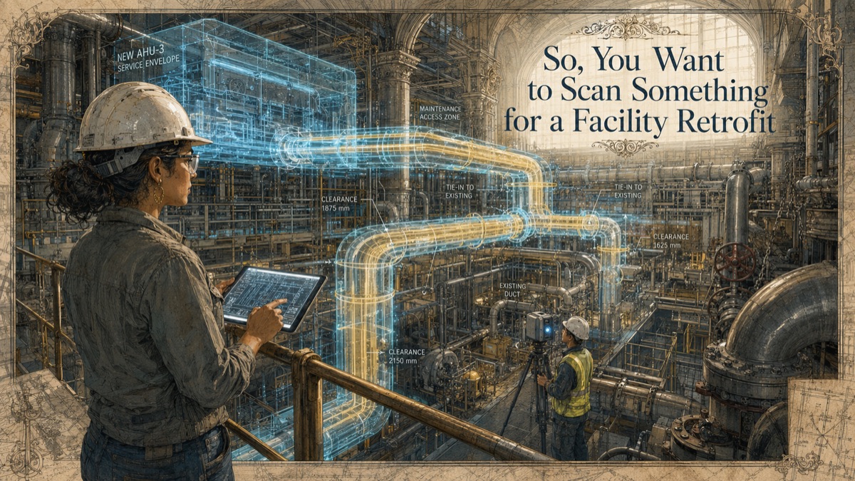
A facility needs a new air handler, upgraded electrical distribution, additional process piping, or a modern controls system. The equipment data looks manageable. The existing drawings suggest there is space. Then the team opens the ceiling, walks the plant room, or checks the route and realizes the facility has been modified so many times that the current system layout is its own design problem. The retrofit is not only about installing something new. It is about threading new work through existing reality.
Retrofit scanning focuses on interfaces, routing, clearances, access, equipment envelopes, and live-facility constraints. It helps engineers design around visible structure, MEP, equipment, and envelope conditions before installation crews discover conflicts in the field. It does not identify concealed systems or system performance by geometry alone, so it should be paired with records and engineering review.
Key Takeaway
Retrofit scanning is most valuable when the scope follows the interfaces that control the work: routes, tie-ins, equipment envelopes, clearances, delivery paths, maintenance access, and live-facility restrictions.
The Retrofit Problem: New Systems in Old Space
This is why GDS treats scanning as a decision-support workflow, not just a technical field activity. The question is not simply, "Can we scan it?" The more useful question is, "What decision must the data support, and what evidence will make that decision safer?"
Why Retrofits Need Better Existing Conditions
Retrofits are often more difficult than remodels because they affect systems, not just space. Ductwork, piping, cable tray, conduit, equipment, shafts, penetrations, structure, and maintenance access all compete for limited space. Old drawings may show design intent, but not field rerouting or later modifications.
A retrofit team needs to know where the existing systems actually are, where the new systems can pass, and where the critical interfaces are located. That is a spatial problem before it is a design problem.
The Five-Phase Retrofit Interface Pipeline
Phase 1 - Define the system change
Identify what is being replaced, added, rerouted, or connected, and which existing interfaces control the design.
Phase 2 - Map the visible constraint environment
Capture the rooms, ceiling plenums, shafts, roofs, plant areas, route corridors, structural constraints, equipment footprints, and access paths that affect the retrofit.
Phase 3 - Create interface-ready deliverables
Develop point clouds, drawings, CAD/BIM, equipment envelopes, sections, or coordination models focused on the retrofit scope.
Phase 4 - Coordinate proposed work against measured conditions
Check routing, clearances, tie-ins, penetrations, maintenance access, and installation sequence before procurement or construction commitment.
Phase 5 - Preserve the updated system record
After the retrofit, update the facility documentation so future maintenance and projects do not return to the same uncertainty.
What to Capture
The scan should focus on visible MEP, plant rooms, risers, shafts, roofs, structural constraints, equipment envelopes, and routes from delivery point to installation point. A retrofit scan may require multiple access windows, especially in occupied buildings or active production facilities.
The scope should also identify what will not be captured. If ceiling areas are inaccessible, if systems are insulated, if labels are unreadable, or if equipment cannot be safely approached, those limitations should be recorded so engineers do not rely on missing information.
Coordination Value
The point cloud or model can be federated with proposed retrofit design to check clearances, routing, penetrations, and maintenance access. This is especially useful when new systems must connect to existing equipment or pass through congested ceiling zones.
The strongest deliverable is not necessarily the most detailed model. It is the deliverable that answers the retrofit question. A route study may need sections and clearance diagrams. A plant-room replacement may need equipment envelopes and connection points. A large MEP upgrade may require a task-specific existing-conditions BIM model.
What Still Requires Engineering Review
Scanning does not confirm pipe contents, electrical load, equipment capacity, structural adequacy, system performance, code compliance, or safe work methods. Those decisions belong to the engineer, owner, safety team, or authority with the appropriate responsibility. GDS can provide the measured spatial baseline and supporting deliverables when included in scope.
Interactive Project Readiness Check
Select the items your team has already defined. This planning aid does not determine technical acceptance or replace project scoping.
Quick Facts
Continue Reading
The next best article depends on where you are in the project. These suggested reads connect this topic to the next practical decision your team is likely to face.
Frequently Asked Questions
What makes retrofit scanning different from remodel scanning?
Retrofit scanning is usually systems-focused. It emphasizes MEP routing, equipment interfaces, structural constraints, penetrations, maintenance access, and installation corridors.
Can scanning be performed in a live facility?
Often, with appropriate access, safety controls, escorts, and operational coordination. Restricted rooms, energized equipment, vibration, and moving operations may affect scope and schedule.
Can scanning identify pipe or duct sizes?
Visible outside geometry can help estimate sizes, but labels, records, insulation, and engineering review may be needed to confirm nominal size, service, material, or operating status.
Does a retrofit scan need BIM?
Only when BIM supports the decision. Some retrofit studies can be answered with point clouds, sections, equipment envelopes, and drawings. Complex coordination may justify BIM.
What should be defined before scanning?
The retrofit system, route corridors, interface points, critical clearances, access constraints, deliverable format, and review responsibility should be defined before fieldwork.
Connect this article to the right GDS workflow
Most physical-to-digital projects touch more than one service. GDS can help determine whether the right starting point is 3D laser scanning, 3D modeling, reverse engineering, or consulting before scope, pricing, schedule, and deliverables are finalized.
GDS provides nationwide project coverage. Current examples from the GDS locations page include Houston, Dallas, Los Angeles, and Austin.
Ready to Start?
Tell GDS about your asset, your goals, and your deliverable needs. GDS can scope the right scanning, modeling, and reporting for your project.