

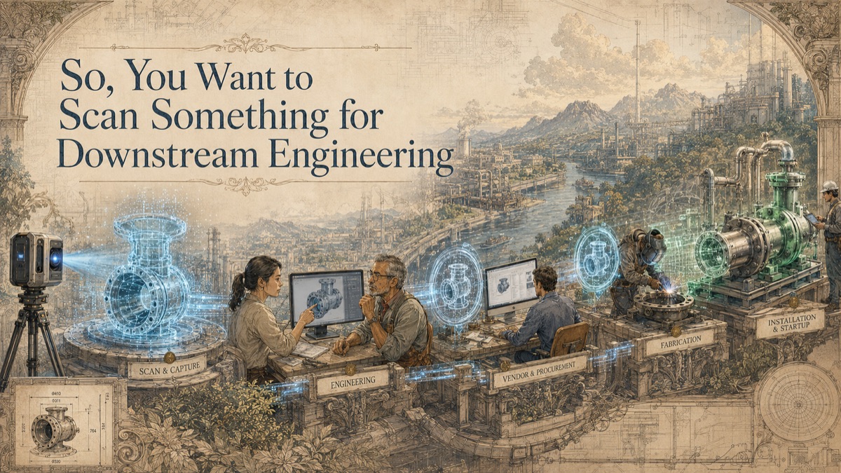
A vendor receives a package that looks complete: drawings, equipment data sheets, interface coordinates, and a model snapshot. They fabricate to the package. The assembly arrives on site and the flange does not line up because the existing nozzle was not where the drawing said it was. The vendor did what they were told. The project team issued the data they had. The problem was that downstream engineering relied on nominal interface information instead of measured conditions.
Downstream engineering is where design data becomes procurement, fabrication, vendor coordination, and installation planning. Scan data can improve this handoff by documenting visible tie-ins, envelopes, routes, clearances, and existing interface geometry. The goal is not to overwhelm vendors with raw point clouds. The goal is to give them usable, controlled interface information with stated uncertainty and limitations.
Key Takeaway
Downstream teams need more than a model file. Procurement, fabricators, vendors, and installers need controlled interface geometry together with units, coordinates, revision status, coverage, assumptions, and approval responsibilities.
The Vendor Interface Problem
This is why GDS treats scanning as a decision-support workflow, not just a technical field activity. The question is not simply, "Can we scan it?" The more useful question is, "What decision must the data support, and what evidence will make that decision safer?"
Why Downstream Engineering Needs Measured Interfaces
Downstream work often fails at interfaces, not in the middle of new design. A vendor can build a perfect skid that still fails to install if the existing foundation, nozzle, pipe, cable tray, or access route was wrong in the package.
Scan data reduces the likelihood that vendors design to outdated drawings. It can also help engineering define realistic interface tolerances and identify where field adjustment should be expected.
The Five-Phase Interface Data Handoff Pipeline
Phase 1 - Identify downstream users
List vendors, fabricators, subcontractors, procurement teams, and installers who will rely on existing-condition geometry.
Phase 2 - Define interface-critical geometry
Identify tie-ins, nozzles, openings, equipment envelopes, support points, routes, penetrations, and access constraints.
Phase 3 - Capture and verify interface data
Use targeted scanning, supplemental checks, or direct measurement when the interface is critical enough to require added confidence.
Phase 4 - Package the data for use
Provide controlled drawings, coordinate tables, simplified models, sections, point clouds, or interface reports in formats the recipient can use.
Phase 5 - Manage revisions and feedback
Track changes, vendor questions, supplemental scans, and approved adjustments through document control.
What to Give Vendors
Vendors rarely need the entire facility scan. They need the parts that affect their package: connection coordinates, orientations, clearance envelopes, nearby obstructions, route constraints, and the coordinate basis. A simplified interface model or controlled report may be more useful than an enormous point cloud.
The data handoff should include revision, units, coordinate system, measured-versus-modeled status, capture date, and limitations. Do not communicate critical tie-in data informally when the information will drive fabrication.
Material Takeoff and Specification Support
Scan-informed routing can support more realistic material takeoffs because design routes are based on visible constraints instead of assumptions. It can also support cable routing, support locations, equipment envelopes, and fabrication planning.
However, quantities and specifications remain engineering outputs. The scan supplies geometry; it does not choose materials, approve specifications, or determine code compliance.
Managing the Supply Chain
The further data travels from the field, the easier it is for context to disappear. A coordinate table without coordinate basis is dangerous. A model without status can be misunderstood. A screenshot without scale can create ambiguity.
A good downstream package makes the measured data usable and auditable. It should be clear what was measured, what was modeled, what was assumed, what was excluded, and who must approve changes.
Interactive Project Readiness Check
Select the items your team has already defined. This planning aid does not determine technical acceptance or replace project scoping.
Quick Facts
Continue Reading
The next best article depends on where you are in the project. These suggested reads connect this topic to the next practical decision your team is likely to face.
Frequently Asked Questions
What is downstream engineering in this context?
It is the work that turns design into procurement, vendor, fabrication, and construction packages that rely on interface geometry.
Do vendors need the full point cloud?
Usually not. Most vendors need a controlled interface package: coordinates, sections, simplified models, drawings, or selected cloud extracts.
Can scan data improve material takeoff?
It can support more realistic routing and quantities when visible constraints affect the route. Final quantities remain part of the engineering and procurement process.
What makes tie-in data risky?
Tie-in data is risky when it is based on old drawings, unclear coordinate systems, missing units, undocumented assumptions, or unverified field conditions.
When should interface scanning occur?
As close as practical to the package issue or fabrication decision, especially when plant conditions can change between design and procurement.
Connect this article to the right GDS workflow
Most physical-to-digital projects touch more than one service. GDS can help determine whether the right starting point is 3D laser scanning, 3D modeling, reverse engineering, or consulting before scope, pricing, schedule, and deliverables are finalized.
GDS provides nationwide project coverage. Current examples from the GDS locations page include Houston, Dallas, Baton Rouge, and Los Angeles.
Ready to Start?
Tell GDS about your asset, your goals, and your deliverable needs. GDS can scope the right scanning, modeling, and reporting for your project.