

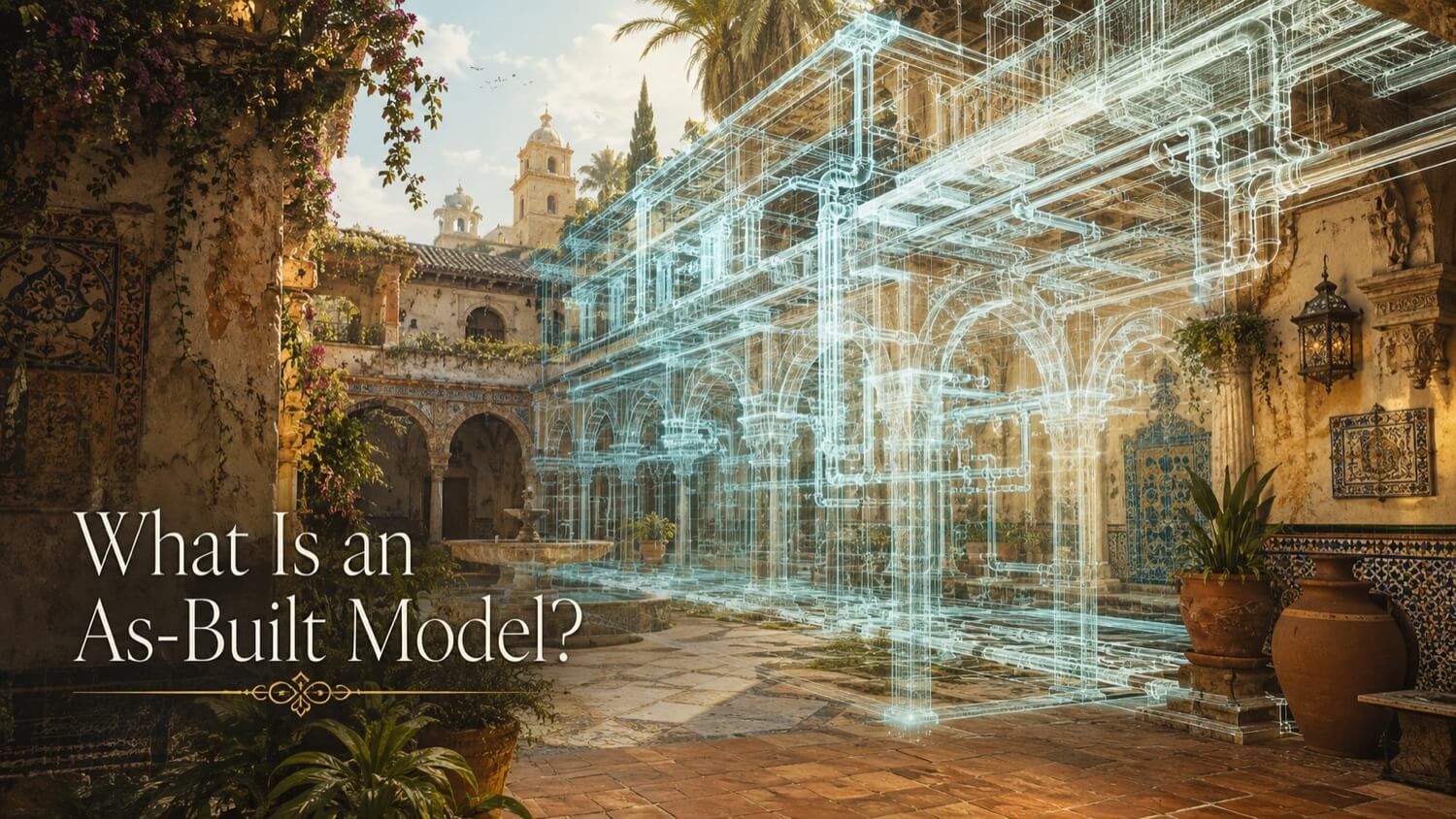
An as-built model is a three-dimensional digital model that documents a completed physical asset , a facility, structure, or piece of installed equipment , exactly as it exists in the real world at the time of survey. Unlike design drawings, which show idealized geometry, or construction documents, which show planned geometry, an as-built model captures actual physical deviations: the concrete slab that settled 12 mm, the structural steel column that bowed under load, the pipe run that was field-rerouted during construction to avoid a conflict.
An as-built model is the authoritative geometric record of what was actually built , a foundation for renovation design, facility management, regulatory compliance, and insurance documentation.
Documenting Physical Reality, Not Design Intent
Construction and installation always deviate from design drawings. Steel fabrication tolerances, concrete forming variations, field routing decisions, and decades of settling and thermal cycling mean that no installed facility matches its original design drawings exactly. In critical applications , installing new equipment into an existing plant, designing tie-in connections, verifying safety clearances , relying on original design drawings rather than the actual installed geometry introduces clash risk, rework, and schedule delays.
As-built models eliminate this risk by replacing the design drawing assumption with a measured, surveyed geometric record of what is physically present.
How GDS Produces As-Built Models
GDS as-built models begin with a registered, quality-controlled point cloud captured by terrestrial LiDAR scanning. The point cloud provides the dimensional backbone for the model. Walls, columns, pipes, equipment, floor slabs, and structural connections can be captured as high-density spatial data, with project accuracy and coordinate control defined by the selected scope and control strategy.
GDS BIM engineers then import the point cloud into Autodesk Revit (or Navisworks, AutoCAD, Bentley MicroStation, or IFC-compatible platforms per client specification) and model each element by tracing over the point cloud underlay:
- Structural steel members are modeled to their actual installed centerlines and profile dimensions
- Concrete slabs are modeled with their actual elevation and slope, including as-built deviations
- Pipe systems are modeled with actual centerlines, diameters, and as-run routing
- Equipment is placed at its surveyed coordinate location with correct envelope dimensions
- Architectural elements are modeled at their actual face positions, not design intent positions
The resulting BIM model contains the real-world geometry of the facility , not the idealized geometry of a drawing.
Level of Development (LOD) and Level of Accuracy (LOA)
Two independent frameworks govern how completely a GDS as-built model is built and how precisely it represents physical coordinates. Specifying both LOD and LOA at project scoping is the single most important decision affecting as-built model cost and utility.
LOD Framework (BIMForum)
The Level of Development (LOD) specification, published by the BIMForum, defines the semantic completeness and reliability of modeled elements:
| LOD | Description | Typical Application |
|---|---|---|
| LOD 100 | Conceptual placeholder , approximate size and location | Master planning |
| LOD 200 | Approximate geometry , generic shape, size, location | Schematic coordination |
| LOD 300 | Precise geometry , accurate shape, size, location, orientation | Design and clash detection |
| LOD 350 | Precise geometry with physical connections and interfaces | Fabrication coordination |
| LOD 400 | Fabrication-level detail with all components | Manufacturing BIM |
| LOD 500 | Field-verified, as-installed element data | Operations and maintenance |
For most facility as-built programs, GDS delivers between LOD 300 and LOD 350 , enough geometric precision for tie-in design, clash detection, and equipment installation planning.
LOA Framework (USIBD)
The Level of Accuracy (LOA) specification, published by the US Institute of Building Documentation (USIBD), defines the geometric precision of modeled elements relative to real-world physical coordinates:
| LOA | Allowable Tolerance Band | Description |
|---|---|---|
| LOA 10 | ±300 mm (±12 in) | Approximate , GPS or sketch-level |
| LOA 20 | ±75 mm (±3 in) | Reconnaissance-grade survey |
| LOA 30 | ±15 mm (±0.6 in) | Standard measured survey |
| LOA 40 | ±5 mm (±0.2 in) | High-precision field survey |
| LOA 50 | ±1 mm (±0.04 in) | High-precision verification when included in scope |
For renovation and tie-in design projects, GDS targets LOA 30 to 40. For precision metrology projects involving off-site prefabrication and modular fit-up, LOA 50 is specified.
Applications of As-Built Models
| Application | Why As-Built Is Required |
|---|---|
| Brownfield renovation and expansion | Existing geometry must be confirmed before new design begins |
| Off-site prefabrication | Skid and module dimensions must match actual tie-in locations |
| Clash detection | New design is tested against real, measured existing conditions |
| Insurance and regulatory documentation | Physical record of facility at a specific date |
| Facilities management (CMMS/CAFM) | Accurate geometry underpins equipment location databases |
| Decommissioning and demolition | Safe sequencing requires confirmed geometric relationships |
Quick Facts
Continue Reading
The next best article depends on where you are in the project. These suggested reads connect this topic to the next practical decision your team is likely to face.
FAQ
What is the difference between an as-built model and an as-designed model?
An as-designed model represents the nominal, intended geometry from engineering drawings , perfect planes, plumb columns, exact dimensions. An as-built model documents what was actually constructed, capturing deviations such as settled foundations, bowed structural members, and field-rerouted piping.
What LOD should I specify for a brownfield renovation project?
LOD 300 is appropriate for most brownfield tie-in design and clash detection work. LOD 350 is recommended when fabrication-level connections, support attachments, and discipline interfaces must be modeled. LOD 500 is reserved for facility management programs requiring operational and maintenance data embedded in model elements.
How long does it take GDS to produce an as-built model?
Timeline depends on facility size, LOD specification, and the number of systems to be modeled. A single-building interior at LOD 300 typically requires 3 to 6 weeks from scan to delivered model. Large industrial facilities at LOD 350 with multiple disciplines commonly require 8 to 16 weeks.
Connect this article to the right GDS workflow
Most physical-to-digital projects touch more than one service. GDS can help determine whether the right starting point is 3D laser scanning, 3D modeling, reverse engineering, or consulting before scope, pricing, schedule, and deliverables are finalized.
GDS lists nationwide coverage from its locations page, including posted major metropolitan areas such as Houston, Dallas, San Antonio, Austin, Los Angeles, San Diego, San Jose, Long Beach, Fort Worth, Irvine, Riverside, New Orleans, Baton Rouge, Shreveport, Las Vegas, and Beverly Hills.
Document Your Facility Before You Renovate
GDS as-built models provide the verified geometric foundation your engineering team needs , LOD 300 to 350, LOA 30 to 40, in Revit, IFC, or AutoCAD format.