

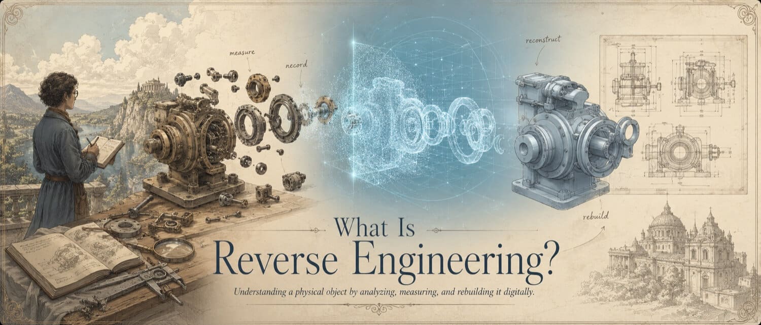
Reverse engineering is the systematic engineering process of analyzing a physical object to recreate its original design specifications, dimensions, and manufacturing parameters. It is not simply "photocopying" a shape with a 3D scanner. It is a disciplined technical workflow where engineers capture the physical reality of a component, identify and quantify the effects of wear, fatigue, and damage, and then mathematically correct those defects. The goal is a fully validated digital model representing the ideal, intended design, ready for CNC machining, additive manufacturing, or long-term technical documentation.
How GDS Can Help
Most physical-to-digital projects touch more than one discipline. GDS can support the workflow from field capture through usable engineering deliverables with 3D laser scanning, 3D modeling, reverse engineering, and consulting.
GDS lists coverage across major metropolitan areas including Houston, Dallas, San Antonio, Austin, Los Angeles, San Diego, San Jose, Long Beach, Fort Worth, Irvine, Riverside, New Orleans, Baton Rouge, Shreveport, Las Vegas, and Beverly Hills. See the current GDS locations page for posted service areas.
Scope note: Specific tolerances, certification requirements, deliverables, schedules, reports, site control, and acceptance criteria should be defined in the quote, proposal, or statement of work for the individual project.
Restoring Design Intent
Every manufactured component degrades from the moment it enters service. Bearing bores enlarge. Shaft diameters shrink. Casting walls warp under thermal cycles. If a replacement part is manufactured by copying the worn geometry exactly, those defects transfer directly into the new component, shortening its service life from the first day of operation.
GDS engineers approach reverse engineering as a design restoration process, not a copying exercise. The physical object serves as the primary dimensional reference, but engineering judgment, geometric constraint logic, and knowledge of standard manufacturing tolerances are applied to reconstruct the component as it was originally designed to be.
The Technical Reconstruction Process
To reconstruct design intent with verifiable accuracy, GDS executes a structured, five-step analytical workflow.
Step 1 , Physical Evaluation & Damage Assessment
Before scanning begins, the component is examined to catalog functional surfaces, mating interfaces, and visible wear or failure modes. Key questions answered at this stage:
- Which surfaces are functional (bearing, sealing, mating) vs. cosmetic?
- Where has material been lost due to wear, corrosion, or fracture?
- Are any features (threads, keyways, internal passages) inaccessible to optical scanning?
This assessment drives every decision downstream, from scanner selection to the degree of dimensional rationalization required.
Step 2 , Optical Data Capture
High-resolution structured-light or blue-laser scanners project a dense pattern of light across the component surface, recording millions of precise 3D spatial coordinates per second. The scanner never contacts the part, eliminating deformation risk on delicate or fractured surfaces.
For highly reflective surfaces (polished chrome, stainless steel) or transparent materials (glass, clear polymers), GDS metrologists apply a temporary, removable matte scanning powder to ensure sufficient laser return signal. For internally threaded features that optical scanners cannot resolve, physical thread gauges are used and standard thread profiles are modeled manually.
Step 3 , Data Cleanup & Alignment
Raw scan data contains noise from scanner positioning, ambient reflections, and environmental vibration. GDS engineers filter this noise and align all scan positions into a single, unified coordinate system. For complex assemblies requiring multiple scan setups, global adjustment routines are executed to prevent coordinate drift, the gradual accumulation of small alignment errors that can produce millimeter-scale offsets in large parts.
Step 4 , Dimensional Rationalization & Constraint Application
This is the step that separates true reverse engineering from simple scan-and-print workflows. A GDS engineer sketches parametric features directly over the cleaned mesh, applying geometric intelligence:
- Concentricity: Worn bearing bores are restored to their nominal centerlines rather than copied with their wear-induced eccentricity.
- Perpendicularity and Parallelism: Machined mating faces are constrained back to their design relationships, even when physical wear has degraded them.
- Standard Nominal Dimensions: Measured values are rationalized to standard engineering dimensions (e.g., a bore measuring 49.87 mm is restored to a nominal 50 mm H7 slip fit).
- Thread Profiles: Standard thread pitches (metric M-series or unified inch UNC/UNF) are applied from gauge measurements rather than guessed from scan data.
The result is a parametric solid model that represents the component's design intent, not its degraded physical state.
Step 5 , Computer-Aided Verification (CAV)
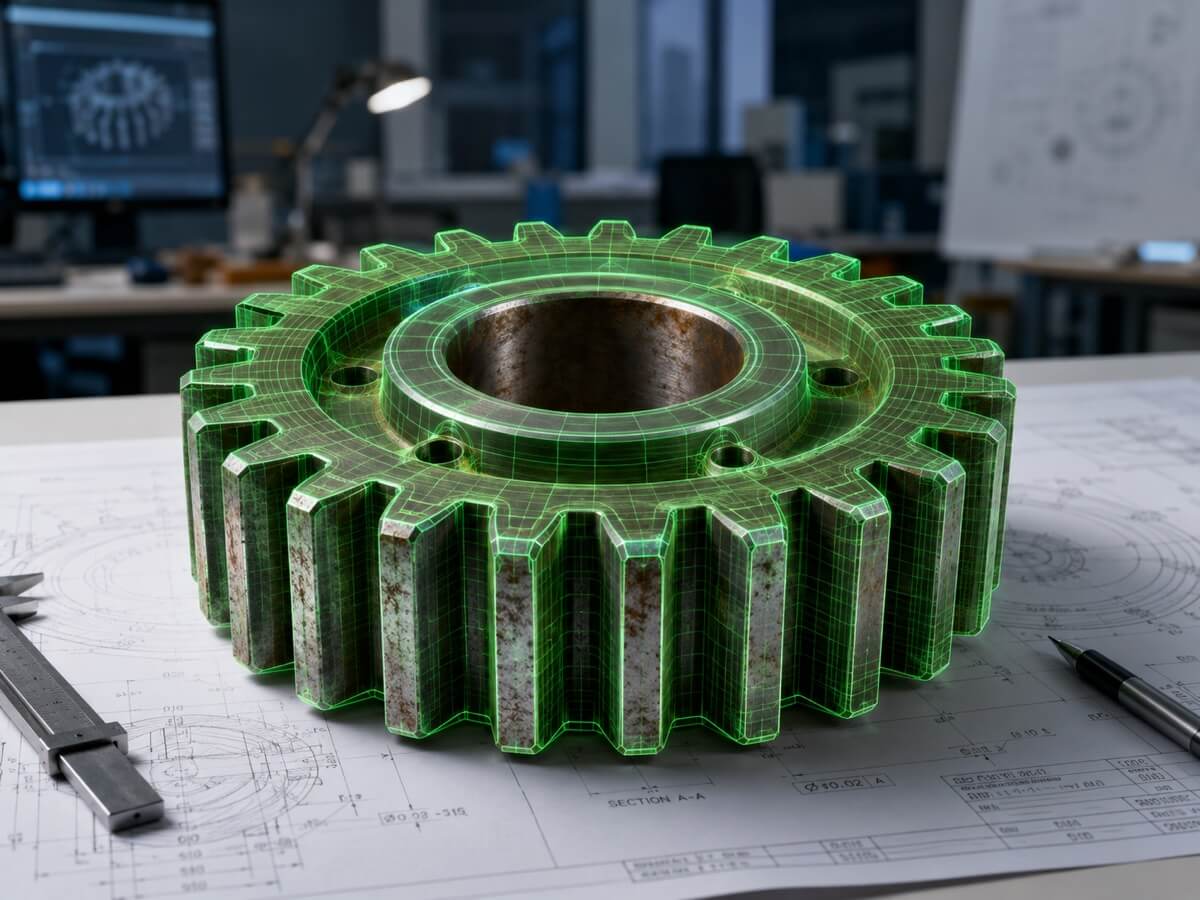
The completed parametric model is imported back into the metrology software and mathematically aligned over the original raw scan data. The software calculates the exact spatial distance from every scanned coordinate to the nearest face of the CAD model, generating a color-coded deviation heatmap:
| Color | Meaning |
|---|---|
| Green | Within specified tolerance (nominal) |
| Red / Warm | Material excess (model undersized relative to scan) |
| Blue / Cool | Material deficit (model oversized relative to scan) |
When included in the project scope, this heatmap provides a useful record of reconstruction quality and comparison against the captured scan data.
What Reverse Engineering Is Not
Reverse engineering is frequently confused with two related but distinct processes:
- Scan-and-Print (As-Scanned Replication): Capturing the worn geometry and manufacturing a direct copy. Fast but propagates all defects into the new part.
- 3D Scanning for Documentation: Capturing a point cloud or BIM model for spatial reference. No parametric reconstruction occurs.
True reverse engineering always produces a clean, fully editable parametric solid model with corrected geometry and verified dimensional accuracy. If the output is only a mesh file, the reverse engineering process is incomplete.
When Reverse Engineering Is the Right Solution
| Scenario | Reverse Engineering Recommended? |
|---|---|
| OEM out of business, no digital files exist | Yes , highest value application |
| Replacement part needed from worn physical sample | Yes |
| Design modification required on legacy component | Yes |
| Documenting facility equipment for record-keeping | No , as-built scanning is appropriate |
| Comparing manufactured part to drawing | No , scan-to-CAD inspection is appropriate |
Quick Facts
Continue Reading
The next best article depends on where you are in the project. These suggested reads connect this topic to the next practical decision your team is likely to face.
FAQ
What is the difference between reverse engineering and 3D scanning?
3D scanning captures a point cloud, a digital record of coordinates representing the object's surface. Reverse engineering uses that scan data as a reference to rebuild a clean, parametric CAD model with corrected geometry, standard dimensions, and manufacturing-ready tolerances. Scanning is the data capture step; reverse engineering is the engineering reconstruction process.
Can you reverse engineer a broken or fractured component?
Yes. GDS engineers routinely reconstruct components with missing sections, fracture surfaces, or heavy corrosion. Missing geometry is restored using symmetry analysis, mating interface logic, and engineering judgment. All reconstructed features are flagged clearly in the deliverable documentation.
What file format does GDS deliver for reverse engineering projects?
A common deliverable is a STEP AP242 (.step) parametric solid model, which is widely compatible with major CAD platforms and many CNC CAM workflows. GDS can also deliver native SolidWorks, CATIA, or Parasolid (.x_t) files depending on client requirements.
How does GDS verify that the reverse-engineered model is accurate?
When included in the project scope, GDS can provide a Computer-Aided Verification (CAV) report. The final CAD model can be aligned over the original raw scan data, and software can calculate deviations across the captured surfaces, producing a color-coded heatmap. This report is delivered alongside the CAD files as a traceable quality record.
How long does a reverse engineering project take?
A single precision mechanical component typically moves from initial scan to verified STEP file delivery in 3 to 10 business days, depending on geometric complexity and the degree of dimensional rationalization required. Rush scheduling is available for critical production downtime situations.
Need a Replacement Part Fast?
Send us clear photos and approximate dimensions. GDS will scope your reverse engineering project and provide a project-specific proposal after the required photos, dimensions, use case, and deliverable requirements are reviewed, no drawings required.