

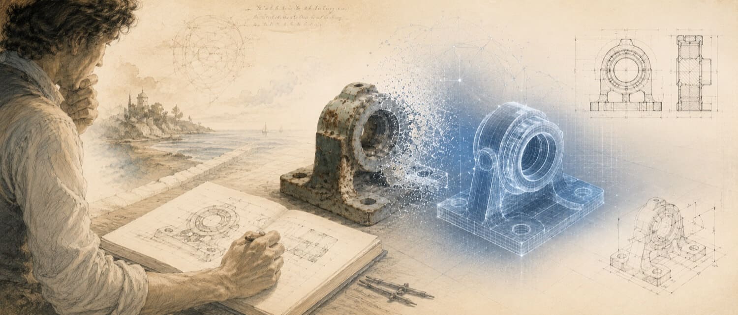
Industrial assets frequently outlast the documentation created during their original manufacture. A custom-cast metal manifold on a primary production line fractures. The facility shuts down. The OEM closed a decade ago. Paper blueprints are missing or destroyed. The broken physical fragment is now the sole source of geometric truth.
Modern CNC machine shops and additive manufacturing bureaus cannot produce replacement components without a mathematically defined, digital CAD model. That gap, between a worn physical object and a validated digital file, is precisely the problem Global Design Solutions (GDS) solves every day.
How GDS Can Help
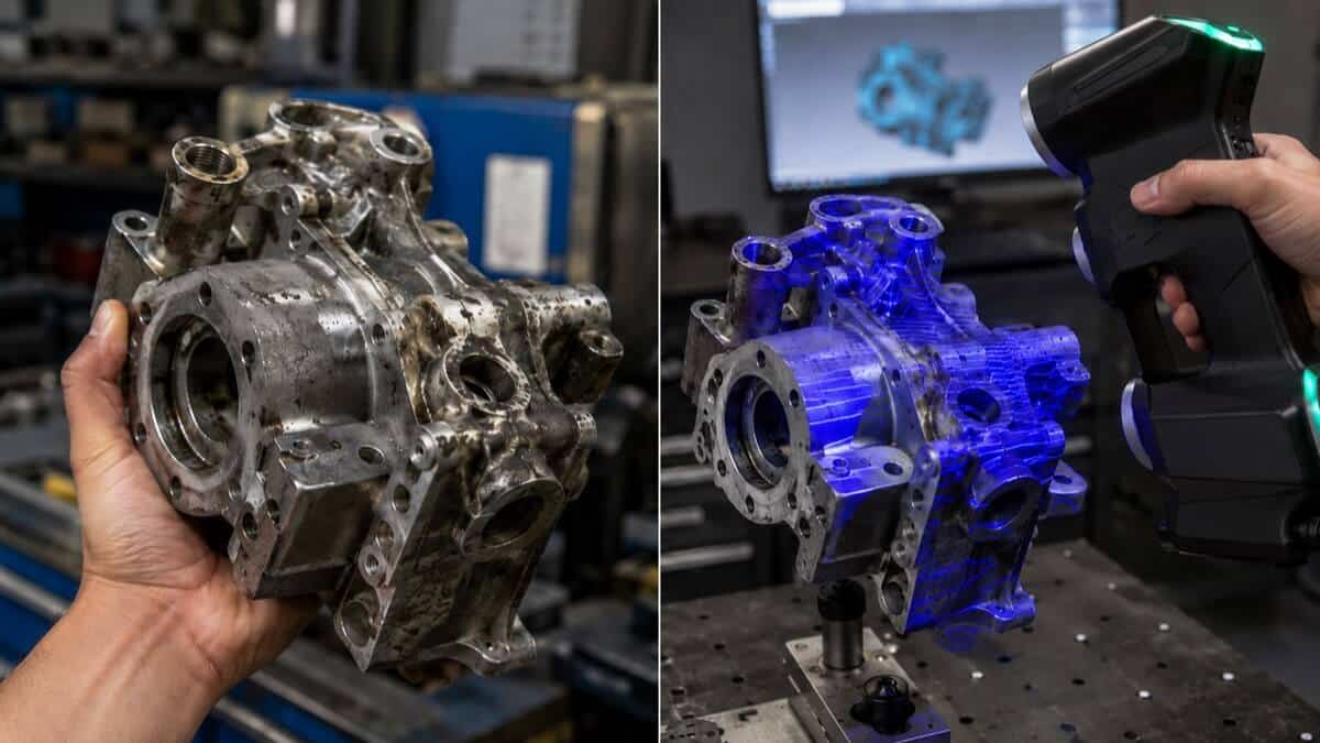
Most physical-to-digital projects touch more than one discipline. GDS can support the workflow from field capture through usable engineering deliverables with 3D laser scanning, 3D modeling, reverse engineering, and consulting.
GDS lists coverage across major metropolitan areas including Houston, Dallas, San Antonio, Austin, Los Angeles, San Diego, San Jose, Long Beach, Fort Worth, Irvine, Riverside, New Orleans, Baton Rouge, Shreveport, Las Vegas, and Beverly Hills. See the current GDS locations page for posted service areas.
Scope note: Specific tolerances, certification requirements, deliverables, schedules, reports, site control, and acceptance criteria should be defined in the quote, proposal, or statement of work for the individual project.
The Obsolete Component Crisis
The scenario above is not an edge case. Across oil and gas, power generation, chemical processing, and heavy manufacturing, thousands of mission-critical components exist without supporting digital documentation. Maintenance teams are forced to either source expensive OEM equivalents (if they still exist), wait months for custom fabrication based on manual measurements, or accept extended unplanned downtime.
Each of these outcomes is avoidable. When the physical component itself still exists, even in a broken or heavily worn state, GDS engineers can capture its complete geometry with project-appropriate accuracy and deliver a validated, manufacturing-ready digital file in a fraction of the time manual measurement would require.
The Physical-to-Digital Pipeline
Translating a physical asset into a validated, downstream digital file requires a sequential, five-phase pipeline executed by experienced metrology and VDC specialists. Every phase is dependent on the accuracy of the phase preceding it, skipping or shortcutting any step introduces compounding error that can make a final CAD model dimensionally unusable.
Phase 1 , Evaluation and Strategy
Before a single scan is captured, GDS engineers evaluate the physical asset to understand its functional environment, mating interfaces, and visible wear patterns. The single most important decision made at this stage is whether to replicate the asset exactly as-is, capturing wear and damage, or to reverse-engineer it back to its nominal, unbroken as-designed state.
Replicating wear produces a part that fits today but will fail sooner. Restoring nominal geometry produces a part built to original design intent, with correct tolerances and functional clearances. For most industrial replacement scenarios, the as-designed reconstruction is the correct engineering choice.
Phase 2 , Data Capture (Scanning)
Non-contact optical or laser scanners project structured light or blue lasers across the object's surface, measuring millions of precise 3D spatial coordinates per second. The scanner never physically contacts the component, eliminating the risk of disturbing fragile or fractured surfaces.
Different scanner technologies are selected based on part size, surface reflectivity, and required accuracy:
| Application | Scanner Type | Typical Accuracy |
|---|---|---|
| Small precision parts | Structured-light scanner | ±0.025 mm |
| Medium industrial components | Blue-laser arm scanner | ±0.05 mm |
| Large facility environments | Terrestrial LiDAR | ±1 to 6 mm |
Phase 3 , Cleaning and Alignment (Registration)
Because scanners operate on a strict line-of-sight basis, complex geometries must be captured from multiple scan positions. These independent datasets are mathematically aligned into a single, unified coordinate system, a process called registration, while background noise, dust reflections, and scanner artifacts are filtered from the raw point cloud.
Registration quality directly determines final model accuracy. GDS engineers execute global adjustment routines and, for large-scale work, tie registration back to a georeferenced survey control network to prevent coordinate drift across multi-scan datasets.
Phase 4 , Polygonization (Creating the Mesh)
The registered point cloud, a dense swarm of floating 3D coordinates, is converted into a continuous, watertight digital surface called a polygon mesh. Meshing software draws flat triangles between adjacent coordinate points, sealing the cloud into an opaque, solid-looking shell.
The mesh at this stage captures the physical reality of the part exactly as scanned: every casting texture, dent, warp, and wear pocket is preserved. It is not yet a parametric CAD model, but it is a highly accurate 3D tracing template.
Phase 5 , Parametric Reconstruction (CAD Modeling)
The polygon mesh represents an accurate visual shell, but it lacks the parametric intelligence required for CNC machining, FEA simulation, or drawing generation. A mechanical CAD specialist uses the mesh as a precise 3D reference template, rebuilding the asset feature-by-feature into clean, mathematically defined solid geometry.
The final deliverable, typically a STEP AP242 file, contains perfect planes, analytically defined cylinders, standard thread profiles, and correct mating tolerances. It is fully editable in any major CAD environment and immediately compatible with CNC CAM software or additive manufacturing slicers.
Choosing the Right Reconstruction Strategy
Three reconstruction strategies serve different project goals:
| Strategy | Output | Best Use Case |
|---|---|---|
| As-Scanned | Mesh (STL/OBJ) | Forensic analysis, 3D printing of existing form |
| As-Built | Mesh or BIM model | Facility documentation, clash detection |
| As-Designed | Parametric STEP | CNC replacement parts, design modification |
For replacement part manufacturing, the as-designed strategy is almost always required. For facility renovation and tie-in design, the as-built model serves as the spatial foundation for downstream engineering coordination.
When to Call a Specialist
Attempting to shortcut the five-phase pipeline, using photogrammetry apps, manual calipers, or consumer scanners, introduces measurement errors that compound through every downstream phase. For components with tight mating tolerances (±0.1 mm or closer), consumer-grade measurement approaches fail at the verification stage.
GDS uses high-accuracy scanning equipment and project-specific quality checks. When verification reporting is included in the scope, GDS can provide deviation maps or dimensional review outputs to show how the model compares to the captured scan data within the agreed tolerance bands.
Quick Facts
Continue Reading
The next best article depends on where you are in the project. These suggested reads connect this topic to the next practical decision your team is likely to face.
FAQ
Do I need original drawings to start a 3D scanning project?
No. GDS's high-accuracy scanning workflow treat the physical asset as the single source of geometric truth. Drawings, blueprints, and original documentation are helpful but never required to begin a digitization project.
How long does the physical-to-digital pipeline take?
Timelines depend on part complexity and required output. A single precision mechanical component can move from scan to validated STEP file in 3 to 10 business days. Large-scale facility scans with full BIM modeling may require 4 to 12 weeks depending on scope and Level of Detail (LOD) specification.
Can a broken or fractured component still be scanned?
Yes. GDS engineers routinely scan broken, heavily corroded, or partially destroyed components. When sections are missing, engineers reconstruct the missing geometry using symmetry analysis, mating interface logic, and engineering judgment, then flag any assumptions in the deliverable documentation.
What is the difference between an as-scanned and an as-designed model?
An as-scanned model captures the physical object exactly as it exists, including all wear, corrosion, and deformation. An as-designed model corrects those defects, restoring the component to its original nominal geometry and manufacturing tolerances, the version required for CNC replacement part production.
What file format will I receive at the end of the project?
GDS delivers the format that matches your downstream process. CNC machining projects receive STEP AP242 (.step) or Parasolid (.x_t) files. Additive manufacturing projects receive STL or 3MF mesh files. Facility documentation projects receive registered point clouds (.e57, .rcp) and/or BIM models (.rvt, .dwg, .nwd, .ifc).
Ready to Digitize Your Component?
Tell us about your part , no drawings required. Our team will scope your project after the required photos, dimensions, use case, and deliverable requirements are reviewed.