

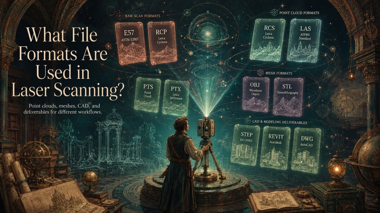
Industrial digitization projects do not use a single file format. From the moment a laser scanner captures raw coordinate data in the field through to the delivery of a finished BIM model or CNC-ready STEP file, projects move through a structured hierarchy of three format tiers, each serving a different technical purpose and compatible with a different set of software tools.
Selecting the correct format at each stage prevents coordinate system conflicts, data loss, software crashes, and, on large-scale projects, tens of thousands of dollars in rework.
How GDS Can Help
Most physical-to-digital projects touch more than one discipline. GDS can support the workflow from field capture through usable engineering deliverables with 3D laser scanning, 3D modeling, reverse engineering, and consulting.
GDS lists coverage across major metropolitan areas including Houston, Dallas, San Antonio, Austin, Los Angeles, San Diego, San Jose, Long Beach, Fort Worth, Irvine, Riverside, New Orleans, Baton Rouge, Shreveport, Las Vegas, and Beverly Hills. See the current GDS locations page for posted service areas.
Scope note: Specific tolerances, certification requirements, deliverables, schedules, reports, site control, and acceptance criteria should be defined in the quote, proposal, or statement of work for the individual project.
A Three-Tier Format Hierarchy
| Tier | Stage | Common Formats |
|---|---|---|
| 1 | Raw Reality Capture (Point Clouds) | .e57, .rcp, .rcs, .las, .laz, .ptx, .pts |
| 2 | Surfacing & Polygonization (Meshes) | .stl, .obj, .ply, .3mf, .fbx |
| 3 | Parametric Reconstruction (CAD/BIM) | .step, .x_t, .rvt, .dwg, .nwd, .ifc |
Each tier's output serves as the input for the next tier. A point cloud feeds the meshing process; a mesh feeds the reverse engineering or BIM modeling process; the CAD/BIM model feeds manufacturing, construction, or facility management systems.
Tier 1 , Raw Reality Capture (Point Cloud Formats)
.e57 , The Neutral Industry Standard
The .e57 format, standardized under ISO 24118, is the preferred neutral container for industrial point cloud data. It stores full-precision 3D coordinates, reflectance intensity values, true-color RGB imagery, scanner metadata (serial number, calibration records, acquisition date), and multi-scan project organization within a single compressed binary file.
Because .e57 is hardware-agnostic, it opens without translation in all major point cloud processing platforms including Autodesk ReCap, Leica Cyclone, Faro Scene, PolyWorks, and CloudCompare. GDS delivers .e57 as the primary archival and exchange format on all facility scanning projects.
.rcp / .rcs , Autodesk Native
The .rcp (Reality Capture Project) and .rcs (Reality Capture Scan) formats are Autodesk's proprietary point cloud container. .rcp is the project-level index file that references one or more .rcs individual scan files. For clients operating in the Autodesk ecosystem, Revit, AutoCAD, Navisworks, .rcp/.rcs files load instantly without conversion, with native indexed access optimized for large dataset performance.
GDS delivers .rcp packages alongside .e57 for Autodesk-ecosystem clients, enabling immediate point cloud visualization in Revit without intermediate processing.
.las / .laz , Georeferenced Classification
The .las format (and its compressed variant .laz) is the standard for georeferenced aerial and terrestrial survey point clouds. It supports classified point data, every coordinate is assigned a classification code (ground, vegetation, building, water surface) defined by the American Society for Photogrammetry and Remote Sensing (ASPRS). LAZ compression reduces file size by 80 to 90% relative to LAS with no data loss.
LAS/LAZ is the preferred format for civil engineering, GIS, and land survey workflows where point clouds must be integrated with survey control networks, GIS platforms, or civil design software such as Autodesk Civil 3D or Bentley OpenSite Design.
.ptx / .pts / .ply , Scanner-Native Formats
- .ptx: Leica scanner native format. Contains per-scan transformation matrices and intensity data. Requires conversion for most non-Leica software.
- .pts: Simple ASCII or binary coordinate list. Human-readable but large and slow to process at scale.
- .ply: Versatile open format storing coordinates, color, intensity, and custom per-point data. Widely supported in research and open-source tools.
Tier 2 , Surfacing and Polygonization (Mesh Formats)
| Format | Primary Use | Key Characteristics |
|---|---|---|
| .stl | 3D printing, deviation analysis | Universal; unitless; geometry only |
| .obj | Visualization, textured models | Includes UV maps and material libraries |
| .ply | Research, colored mesh delivery | Stores per-vertex color and custom fields |
| .3mf | Professional additive manufacturing | Explicit units; compressed; material data |
| .fbx | Animation, VR/AR visualization | Rich scene data; Autodesk native |
For industrial metrology and reverse engineering, GDS delivers .stl (watertight, high-resolution) for 3D printing and deviation analysis. For client visualization and digital twin rendering, .obj with photographic texture mapping provides the most detail-rich output.
Tier 3 , Parametric Reconstruction (CAD/BIM Formats)
| Format | Platform | Use Case |
|---|---|---|
| .step / .stp | Universal CAD | CNC machining, FEA, engineering drawings |
| .x_t / .x_b | Parasolid-based CAD | High-fidelity B-Rep exchange, assembly preservation |
| .rvt | Autodesk Revit | Intelligent BIM models for AEC projects |
| .dwg | AutoCAD | 2D drawings, coordinate-accurate 3D layouts |
| .nwd | Autodesk Navisworks | Multi-discipline clash detection and coordination |
| .ifc | Open BIM (ISO 16739) | Interoperable BIM exchange across all platforms |
GDS delivers .step AP242 for mechanical reverse engineering and .rvt for facility Scan-to-BIM projects. .ifc is delivered when clients require open-standard BIM interoperability outside the Autodesk ecosystem.
Choosing the Right Format for Your Workflow
| If Your Next Step Is... | Request This Format |
|---|---|
| Import into Revit or AutoCAD | .rcp / .rcs or .e57 |
| CNC machining | .step AP242 or .x_t |
| 3D printing | .stl or .3mf |
| Clash detection in Navisworks | .nwd or .rvt |
| GIS / civil design | .las or .laz |
| Open BIM coordination | .ifc |
| Archival and future-proofing | .e57 (point cloud) + .step (CAD) |
Quick Facts
Continue Reading
The next best article depends on where you are in the project. These suggested reads connect this topic to the next practical decision your team is likely to face.
FAQ
What is the best point cloud format for Revit?
Autodesk's native .rcp/.rcs format provides the fastest, most stable point cloud import into Revit without intermediate conversion. GDS delivers .rcp project packages alongside .e57 archival files for all Autodesk-ecosystem clients.
What is the difference between E57 and LAS?
E57 is the general-purpose neutral standard for industrial scanning, storing coordinates, intensity, RGB color, and scanner metadata. LAS is specifically designed for georeferenced aerial and terrestrial survey data, with point classification codes (ground, vegetation, building) used in GIS and civil engineering workflows. For facility scanning, E57 is preferred. For geospatial and site survey, LAS or LAZ is the standard.
Can I receive multiple file formats from the same project?
Yes. GDS routinely delivers multi-format packages: .e57 for archival, .rcp for Revit import, and .step for CNC machining from the same project dataset. Specify all required downstream uses during scoping to ensure every format is included in the deliverable package.
Not Sure Which Format Your Project Needs?
GDS delivers multi-format packages, point cloud, mesh, and parametric CAD, from a single project. Tell us your downstream process and we'll specify the right formats before you commit.