

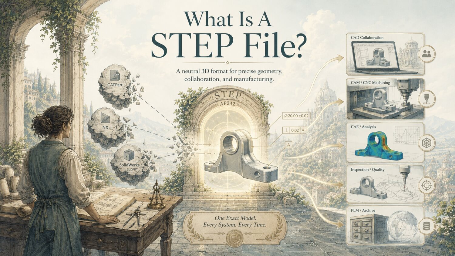
The .step (or .stp) file format, formally codified under ISO 10303, Standard for the Exchange of Product model data, is the universal neutral standard for transferring precise CAD geometry between different software platforms, manufacturing systems, and organizational boundaries. Where mesh formats like STL approximate curved surfaces with flat triangles, a STEP file stores geometry as exact mathematical definitions: a cylinder is described not by thousands of facets, but by a mathematically perfect analytical surface centered at precise coordinates with an exact radius.
This mathematical precision makes STEP the required format for any downstream process that demands dimensional accuracy: CNC machining, injection molding tooling, FEA simulation, engineering drawing generation, and precision inspection.
How GDS Can Help
Most physical-to-digital projects touch more than one discipline. GDS can support the workflow from field capture through usable engineering deliverables with 3D laser scanning, 3D modeling, reverse engineering, and consulting.
GDS lists coverage across major metropolitan areas including Houston, Dallas, San Antonio, Austin, Los Angeles, San Diego, San Jose, Long Beach, Fort Worth, Irvine, Riverside, New Orleans, Baton Rouge, Shreveport, Las Vegas, and Beverly Hills. See the current GDS locations page for posted service areas.
Scope note: Specific tolerances, certification requirements, deliverables, schedules, reports, site control, and acceptance criteria should be defined in the quote, proposal, or statement of work for the individual project.
Boundary Representation (B-Rep) Geometry
STEP files store geometry using Boundary Representation (B-Rep) mathematics. A B-Rep solid is defined by the complete set of surfaces (faces), curves (edges), and points (vertices) that bound its exterior. Each face is defined by an exact mathematical surface type, a plane, a cylinder, a cone, a torus, or a NURBS spline, not by a mesh approximation.
The practical implications are significant:
| Property | STEP (B-Rep) | STL (Mesh) |
|---|---|---|
| Cylindrical surfaces | Mathematically exact | Faceted approximation |
| Curve precision | Infinite (analytical) | Resolution-limited |
| Feature editability | Full parametric editing | Extremely limited |
| CNC toolpath quality | Smooth, continuous paths | Facet-to-facet chatter |
| File size for complex parts | Compact | Very large |
When a CNC CAM programmer opens a STEP file, every curved surface is defined by a mathematical equation that the CAM system can evaluate at any point with zero approximation error, producing smooth, continuous cutting paths and exceptional surface finishes.
Application Protocols: AP203, AP214, and AP242
STEP is not a single monolithic standard. It is organized into Application Protocols (APs) that define which types of product data are included in the file. Selecting the correct AP is critical for preserving the engineering data your downstream process requires.
AP203 , Legacy Geometry Exchange
AP203 is the original STEP standard, supporting 3D solid geometry and assembly hierarchies. It transfers shape, position, and component relationships accurately but carries no visual or manufacturing annotation data. AP203 is widely supported across all CAD platforms and remains sufficient for basic geometry exchange where the receiving party only needs the 3D shape.
AP214 , Geometry Plus Color and Layers
AP214 extends AP203 by adding support for layer structures, custom colors, surface finish designations, and basic Geometric Dimensioning and Tolerancing (GD&T) annotations. AP214 is appropriate when visual organization and basic tolerance data must survive the file transfer, particularly in automotive and aerospace supplier chains.
AP242 , The Modern PMI Standard
AP242 is the current state-of-the-art STEP protocol and GDS's default deliverable for reverse engineering and precision part projects. AP242 supports semantic Product Manufacturing Information (PMI): dimensional tolerances, GD&T callouts, material specifications, and surface finish requirements are embedded directly into the 3D model as machine-readable digital data, not as passive notes or dumb text annotations.
With AP242, a CNC programmer can interrogate the model directly to extract tolerances without referencing a separate 2D drawing. An inspection engineer can load the same file into PolyWorks and automatically generate an inspection plan directly from the embedded PMI. This is the foundation of Model-Based Definition (MBD), the emerging manufacturing standard that eliminates 2D drawing dependency entirely.
Product Manufacturing Information (PMI)
PMI is the collection of manufacturing specifications that must accompany 3D geometry to fully define a part for production:
- Dimensional tolerances (e.g., ±0.05 mm on a bore diameter)
- Geometric tolerances (GD&T callouts: flatness, perpendicularity, true position)
- Surface finish designations (e.g., Ra 0.8 µm on sealing faces)
- Material callouts (e.g., 316L stainless steel per ASTM A276)
- Thread specifications (e.g., M16 × 2.0 - 6H)
In AP203 and AP214 files, PMI is often embedded as 2D annotation text that humans can read but software cannot parse. In AP242, PMI is stored as structured, semantic data that downstream software, CAM, inspection, ERP, can read, validate, and act on without human re-entry.
STEP in the Industrial Digitization Pipeline
In GDS workflows, the STEP file is the terminal deliverable of the reverse engineering pipeline:
Physical Object → Scan → Mesh → Parametric Reconstruction → STEP AP242
The STEP file produced at the end of this pipeline is the engineering-grade digital twin of the physical component, dimensionally accurate, fully editable, and immediately compatible with every major CNC CAM platform, FEA package, and drawing generation suite.
Quick Facts
Continue Reading
The next best article depends on where you are in the project. These suggested reads connect this topic to the next practical decision your team is likely to face.
FAQ
What is the difference between STEP AP203, AP214, and AP242?
AP203 transfers 3D solid geometry and assembly structure only. AP214 adds color, layers, and basic GD&T annotations. AP242 is the current standard, embedding full semantic PMI, tolerances, material callouts, and GD&T, as machine-readable data directly in the 3D model. GDS delivers AP242 for all reverse engineering projects requiring downstream manufacturing.
Can I open a STEP file in any CAD software?
Yes. STEP is the universal neutral CAD exchange format. It opens natively in SolidWorks, CATIA, NX, Creo, Fusion 360, AutoCAD, FreeCAD, and all major CAD platforms without a translator or plugin. PMI data (AP242) is preserved in software that supports semantic PMI reading.
Is a STEP file the same as a native CAD file?
No. A native CAD file (e.g., .sldprt, .catpart, .prt) stores the full parametric feature tree including sketches, design intent, and history. A STEP file stores the final solid geometry without feature history. STEP geometry is fully editable in any receiving CAD platform, but the original feature tree is not preserved. GDS can deliver native SolidWorks or CATIA files in addition to STEP when clients require full design history.
Need a STEP AP242 File from a Physical Part?
GDS delivers verified STEP AP242 parametric solid models from any physical component , complete with CAV deviation report, ready for CNC machining or FEA simulation.