

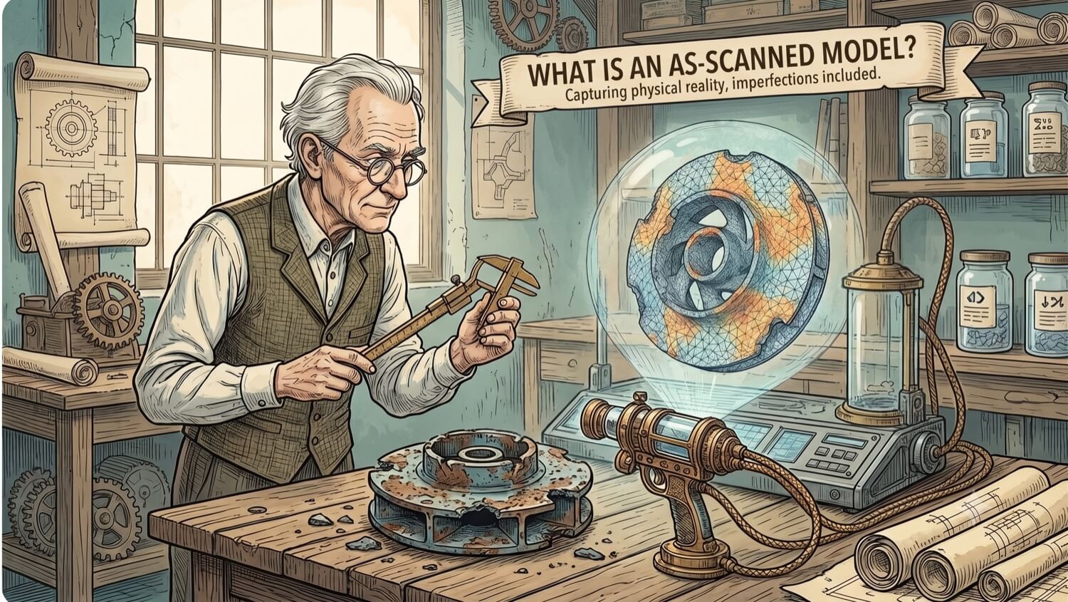
An as-scanned model is a high-resolution digital representation of a physical component captured exactly as it exists at the moment of scanning , without any dimensional correction, idealization, or engineering interpretation applied. Delivered as a high-density polygon mesh, it preserves every dent, wear pocket, corrosion crater, warp, and surface defect with sub-millimeter fidelity.
It is, in the most precise sense, an uncompromised snapshot: a digital record of physical reality at a specific point in time.
The Unvarnished Snapshot of Reality
Most reverse engineering projects aim to correct physical defects , to reconstruct the nominal, as-designed geometry from a worn physical sample. An as-scanned model takes the opposite approach. Rather than correcting wear, it documents it. Rather than idealizing geometry, it preserves it. Rather than inferring design intent, it records physical state.
This makes the as-scanned model the highest-fidelity reference for any engineering task that requires knowing exactly what is physically present , not what was originally designed to be present.
What an As-Scanned Model Contains
An as-scanned mesh delivered by GDS contains:
| Element | Description |
|---|---|
| Full surface geometry | Complete triangulated mesh of all scanned surfaces |
| As-existing deformations | Warps, bows, dents, and settling preserved exactly |
| Wear surfaces | Material loss from friction, corrosion, and erosion mapped precisely |
| Fracture surfaces | Crack profiles and fracture planes captured at scan resolution |
| Texture data (optional) | Photorealistic RGB color or intensity-mapped grayscale |
What an as-scanned model does not contain: parametric features, standard nominal dimensions, tolerances, GD&T callouts, thread definitions, or any engineering correction. It is a surface mesh, not a parametric solid.
How GDS Produces an As-Scanned Model
1. Optical capture: Structured-light or blue-laser scanner records the complete accessible surface geometry at ±0.025 mm accuracy per scan position. 2. Registration: Multiple scan positions are aligned into a unified coordinate system. 3. Mesh generation: The registered point cloud is converted to a high-resolution polygon mesh. 4. Mesh cleanup: Noise spikes, holes from scanner occlusion, and non-manifold edges are repaired. No dimensional correction is applied. 5. Quality inspection: The final mesh is inspected for completeness and watertight closure. 6. Delivery: The as-scanned mesh is delivered in STL, OBJ, or PLY format alongside a scan report documenting capture parameters and known occlusion areas.
Applications of As-Scanned Models
Forensic Failure Analysis
When a component fails in service , fractures, seizes, deforms , the as-scanned model captures the failure state before any disassembly, cleaning, or material testing disturbs the evidence. Engineers can analyze fracture surface profiles, measure crack propagation paths, and calculate the material deformation that preceded failure , all without consuming or altering the physical evidence.
Wear Tracking and Tool Life Monitoring
By scanning a component at multiple points in its service life and comparing the resulting as-scanned meshes, engineers can calculate cumulative material loss, track wear rate, and predict the remaining service life before the next replacement. This serial scanning approach is widely used in die and mold wear monitoring, cutting tool life optimization, and turbine blade erosion tracking.
Deviation Analysis vs. Nominal CAD
The as-scanned mesh serves as the measured reference in scan-to-CAD deviation analysis. When aligned against a nominal STEP model in metrology software (GOM Inspect, PolyWorks), the software calculates the spatial deviation at every mesh vertex , producing a color-coded heatmap that quantifies exactly where the physical component deviates from engineering specification.
3D Printing of As-Existing Geometry
When a forensic replica or reverse mockup is required , for fit testing, training, or mock-up assembly validation , the as-scanned mesh can be sent directly to a 3D printer. The printed replica reproduces the physical component exactly as it exists, including all wear and deformation, without any engineering correction.
As-Scanned vs. As-Built vs. As-Designed
| Model Type | Captures | Corrects | Output Format | Primary Use |
|---|---|---|---|---|
| As-Scanned | Physical state exactly | Nothing | Mesh (STL, OBJ) | Forensics, inspection, wear tracking |
| As-Built | Installed facility state | Nothing | BIM model | Facility documentation, renovation design |
| As-Designed | Original nominal geometry | All defects | STEP AP242 | CNC machining, replacement parts |
Quick Facts
Continue Reading
The next best article depends on where you are in the project. These suggested reads connect this topic to the next practical decision your team is likely to face.
FAQ
What is the difference between an as-scanned model and a reverse-engineered model?
An as-scanned model captures the physical component exactly as it exists , all wear and defects included , with no engineering correction. A reverse-engineered (as-designed) model analyzes the scan, corrects defects, and rebuilds the geometry to nominal design intent. As-scanned models are used for inspection and forensics; as-designed models are used for CNC machining replacement parts.
Can an as-scanned model be used directly for 3D printing?
Yes, when the mesh is prepared as a watertight STL or 3MF and the printer requirements are understood. The printed item represents the component in its captured condition, which can be useful for training mockups, fit checks, and forensic visualization, but it may also reproduce wear, damage, or distortion and should not be assumed suitable as a functional replacement part.
How is an as-scanned model used in quality inspection?
The as-scanned mesh can be imported into inspection or comparison software and aligned against a nominal STEP CAD model when that analysis is part of the project scope. The software calculates spatial deviation across the evaluated mesh surface, producing a color-coded deviation heatmap that quantifies where the physical component is in excess (material too thick) or in deficit (material too thin) relative to engineering specifications.
Connect this article to the right GDS workflow
Most physical-to-digital projects touch more than one service. GDS can help determine whether the right starting point is 3D laser scanning, 3D modeling, reverse engineering, or consulting before scope, pricing, schedule, and deliverables are finalized.
GDS lists nationwide coverage from its locations page, including posted major metropolitan areas such as Houston, Dallas, San Antonio, Austin, Los Angeles, San Diego, San Jose, Long Beach, Fort Worth, Irvine, Riverside, New Orleans, Baton Rouge, Shreveport, Las Vegas, and Beverly Hills.
Need a Forensic Record of Your Component?
GDS delivers high-resolution as-scanned mesh files with full deviation reporting , preserving the physical state of any component exactly as it exists.