

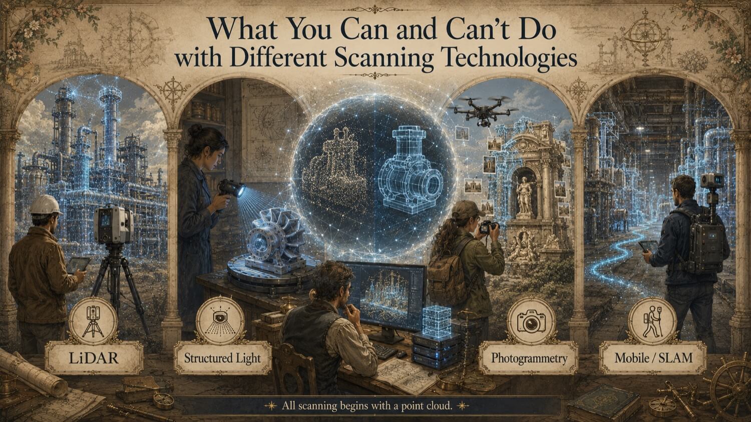
One of the most common misconceptions in the 3D scanning industry is that scanning is a single technology, that a scanner is a scanner, and the only variable is price. In reality, there are five distinct scanning technology families in common industrial use, each with fundamentally different operating principles, accuracy envelopes, working ranges, and optimal applications. Choosing the wrong technology for your project does not just reduce accuracy, it can make the task impossible.
This article explains each technology in plain language: what it is, what it does well, what it cannot do, and when GDS recommends it. By the end, you will know enough to have an informed conversation about scanning technology selection, and to understand why GDS may recommend a different approach than the one you originally expected.
GDS Project Support
Connect This Step to the Right GDS Service
Most physical-to-digital projects involve more than one decision. GDS can help clarify the right capture method, deliverable, file format, and review process through 3D laser scanning, 3D modeling, reverse engineering, and consulting.
GDS lists service coverage across posted metro areas including Houston, Dallas, San Antonio, Austin, Los Angeles, San Diego, San Jose, Long Beach, Fort Worth, Irvine, Riverside, New Orleans, Baton Rouge, Shreveport, Las Vegas, and Beverly Hills. GDS also lists offices in Torrance, California and Houston, Texas. See the current GDS locations page for posted service areas.
Scope note: Accuracy, tolerances, schedules, file formats, review windows, data retention, reporting, site access, safety requirements, and acceptance criteria should be confirmed in the quote, proposal, or statement of work for the specific project.
Technology 1, Terrestrial Laser Scanning (TLS)
What It Is
Terrestrial laser scanning uses a tripod-mounted instrument that emits a rotating laser beam to measure the distance and direction to every point it strikes within its field of view. Modern TLS instruments capture 500,000 to 2,000,000 points per second at ranges of up to 130 metres, building up a dense, highly accurate three-dimensional point cloud of the surrounding environment from each scan position.
What TLS Can Do
- Capture large-scale environments, industrial facilities, structures, infrastructure, at ±1 to 3 mm accuracy
- Operate in daylight, low light, and indoor environments without performance degradation
- Capture complex geometry with full 360° field of view from each scan position
- Generate photographic imagery embedded in the point cloud for visual reference
- Operate in hazardous and classified areas with appropriate instrument selection
- Produce registered point clouds covering areas of thousands of square metres from a single site mobilisation
What TLS Cannot Do
- Capture moving objects accurately, moving machinery, vehicles, and people create artefacts in the scan data
- Access highly confined spaces where the instrument cannot be positioned (ventilation ducts, inside small vessels)
- Capture the underside of objects, the scanner sees only what it has line-of-sight to
- Achieve the sub-0.5 mm accuracy required for precision part inspection or reverse engineering
- Replace a portable CMM for tolerance-critical feature measurement
When GDS Recommends TLS
For any project requiring comprehensive documentation of an existing environment at facility scale, plant documentation, as-built verification, site survey for design, BIM model foundation, TLS is the primary technology. It is the workhorse of industrial scanning and the foundation for Articles 41 and 43.
Technology 2, Structured Light Scanning
What It Is
Structured light scanners project a patterned light (fringe patterns or grids) onto an object surface and capture the distortion of that pattern with one or more high-resolution cameras. The distortion geometry is used to calculate precise surface coordinates. Unlike laser scanning, structured light scanning captures complete surface patches rather than individual point measurements, producing very high-density, very high-accuracy surface data over the object within the scanner's field of view.
What Structured Light Can Do
- Achieve ±0.01 to 0.05 mm accuracy on objects up to approximately one metre in size
- Capture fine surface detail, texture, scratches, weld geometry, casting surface, at very high resolution
- Produce a complete, hole-free mesh of a part surface in a single scan session
- Perform at the accuracy level required for precision reverse engineering and first article inspection
- Operate in controlled lighting environments on stationary objects
What Structured Light Cannot Do
- Scan large environments, working range is typically less than 1 metre
- Scan objects with highly reflective or transparent surfaces without surface preparation (matte spray)
- Operate effectively in direct sunlight (ambient light interferes with the projected pattern)
- Scan objects that cannot be moved or positioned for access to all surfaces
When GDS Recommends Structured Light
For precision part reverse engineering (Article 42), first article inspection, and manufacturing quality inspection (Article 44) where sub-0.1 mm accuracy is required. Not suitable for facility or environmental scanning.
Technology 3, Photogrammetry
What It Is
Photogrammetry derives three-dimensional geometry from overlapping two-dimensional photographs. Software analyses common features across multiple images taken from different positions and reconstructs the three-dimensional geometry of the photographed scene. Modern photogrammetry software can process hundreds or thousands of images into a dense point cloud or mesh model.
What Photogrammetry Can Do
- Capture large-scale environments from UAV (drone) platforms at ±10 to 50 mm accuracy
- Generate textured 3D models with high visual realism, valuable for presentation, visualisation, and heritage documentation
- Cover areas and access locations that ground-based scanning cannot reach (rooftops, tall structures, remote terrain)
- Operate from inexpensive camera equipment compared to laser scanning
- Produce georeferenced models when ground control points are used
What Photogrammetry Cannot Do
- Achieve the ±1 to 3 mm accuracy of terrestrial laser scanning for engineering applications
- Capture poorly textured surfaces accurately (plain concrete, white walls, shiny metal), these surfaces offer insufficient feature contrast for image matching
- Operate effectively in low-light conditions without supplementary lighting
- Penetrate inside structures or into confined spaces from an external UAV platform
- Replace laser scanning for engineering and fabrication applications where millimetre accuracy matters
When GDS Recommends Photogrammetry
For large-area topographic survey, roof and façade documentation, heritage and visual documentation, and applications where the ±10 to 50 mm accuracy envelope is acceptable. GDS often combines photogrammetry (for large-area context) with TLS (for engineering-accuracy detail) on projects that require both.
Technology 4, Mobile Mapping Systems
What It Is
Mobile mapping systems mount laser scanners and cameras on a moving platform, a vehicle, a trolley, a backpack, or a robotic platform, and capture point clouds continuously as the platform moves through the environment. Position is tracked using SLAM (Simultaneous Localisation and Mapping) algorithms or GNSS/IMU integration.
What Mobile Mapping Can Do
- Cover large areas at high speed, a mobile system can scan a warehouse floor or a corridor network in a fraction of the time of static TLS
- Capture areas where setting up a static scanner at multiple positions would be impractical (long corridors, road networks, storage aisles)
- Provide rapid overview scans of large facilities for asset inventory and space planning applications
- Generate data in a continuous, walkthrough format suited to facility management applications
What Mobile Mapping Cannot Do
- Match the accuracy of static TLS, mobile systems typically achieve ±5 to 20 mm rather than ±1 to 3 mm
- Capture fine detail in cluttered environments as reliably as a static scanner with full 360° coverage
- Operate in environments where the platform cannot navigate (stairs, ladders, confined spaces, rough terrain)
- Substitute for static TLS where engineering-accuracy deliverables are required
When GDS Recommends Mobile Mapping
For large-facility rapid survey, asset inventory scanning, and space utilisation assessments where speed is prioritised over engineering-grade accuracy. Often used as a first pass to identify areas requiring higher-accuracy static scanning.
Technology 5, Handheld Laser Scanning
What It Is
Handheld scanners combine a laser line or structured light sensor with an inertial measurement unit (IMU) and camera to track position as the operator moves the scanner freely around an object. They offer portability and access flexibility at the cost of accuracy compared to fixed instruments.
What Handheld Scanning Can Do
- Access confined spaces, complex geometry, and areas where fixed instruments cannot be positioned
- Scan medium-sized objects (0.1 m to approximately 3 m) quickly without fixturing
- Capture geometry at ±0.1 to 0.5 mm accuracy, adequate for many reverse engineering and as-built applications
- Provide rapid turnaround for small-scope scanning tasks
What Handheld Scanning Cannot Do
- Match the accuracy of structured light or arm-mounted CMM scanning for precision applications
- Maintain accuracy over large areas, drift accumulates over extended scan paths
- Capture fine surface texture at the resolution of structured light systems
When GDS Recommends Handheld Scanning
For medium-precision reverse engineering, as-built capture of complex assemblies in confined spaces, and rapid inspection of moderate-sized components where structured light accuracy is not required.
Summary, Choosing the Right Technology
| Technology | Accuracy | Best Scale | Indoor/Outdoor | Best Application |
|---|---|---|---|---|
| Terrestrial Laser Scanning | ±1 to 3 mm | Facility/Environment | Both | As-built, facility documentation, BIM foundation |
| Structured Light | ±0.01 to 0.05 mm | Part/Component | Indoor | Precision RE, FAI, manufacturing inspection |
| Photogrammetry | ±10 to 50 mm | Large Area/UAV | Outdoor | Topography, façade, visualisation |
| Mobile Mapping | ±5 to 20 mm | Large Indoor Area | Both | Rapid facility survey, asset inventory |
| Handheld Laser | ±0.1 to 0.5 mm | Medium Object | Both | Confined space RE, quick as-built |
Quick Facts
Continue Reading
The next best article depends on where you are in the project. These suggested reads connect this topic to the next practical decision your team is likely to face.
FAQ
Can scanning see through walls, floors, or pipe insulation?
No. All optical scanning technologies, laser scanning, structured light, and photogrammetry, capture only visible surfaces. Walls, floors, ceilings, and insulation block the scanner's line of sight. Scanning behind walls requires access through penetrations or the use of supplementary technologies (ground-penetrating radar, pipe inspection cameras). Insulated pipes are scanned at their insulation outer surface, not at the pipe wall, if the pipe wall geometry is required, insulation must be removed or separate measurements taken.
Why does my scan data have holes or gaps?
Gaps in scan data (called 'shadows' or 'occlusions') occur where the scanner's line of sight was blocked by an intervening object. Every object in a scan environment casts a shadow in the scan data behind it. GDS manages occlusion by planning scan positions that provide overlapping coverage from different angles, reducing shadows in areas critical to the deliverable scope. Some occlusion is unavoidable in complex industrial environments, When included in the scope, GDS can document significant data gaps and advise on supplementary measurement where required.
Can you scan in the dark or in low-light conditions?
Laser scanning (TLS and handheld) does not depend on ambient lighting, the laser provides its own illumination and measures distance using time-of-flight or phase shift, not reflected light intensity for geometry. Low-light environments typically do not affect laser geometry the same way they affect photography, but site conditions, surface conditions, and capture settings still matter. However, the integrated photography captured alongside the scan for visual reference does require adequate lighting for colour accuracy. GDS can plan supplemental lighting for embedded photography when low-light conditions make visual reference images important.
What happens with shiny or reflective surfaces?
Highly reflective surfaces (polished metal, mirrors, wet surfaces) and transparent surfaces (glass, clear plastics) are challenging for all optical scanning technologies. Laser scanning typically returns noisy or missing data on mirror-polished surfaces. Structured light scanning may require temporary matte scanning spray or another mitigation method for reflective surfaces before capture. GDS identifies surface conditions during project scoping and plans appropriate mitigation, including supplementary measurement for surfaces where scanning alone is insufficient.