

Receiving your scan deliverables is not the end of the process , it is the beginning of a different one. The data has been captured, processed, and submitted for review according to the agreed scope. Now the question shifts from "how do we collect the data?" to "how do we use it?"
For many organizations, particularly those commissioning professional scanning for the first time, this transition is where momentum stalls. The data arrives. It goes to one person who knows how to open it. That person is busy. The files sit in a folder. Three weeks later, someone asks if the scan data is available yet , and technically it has been there the whole time.
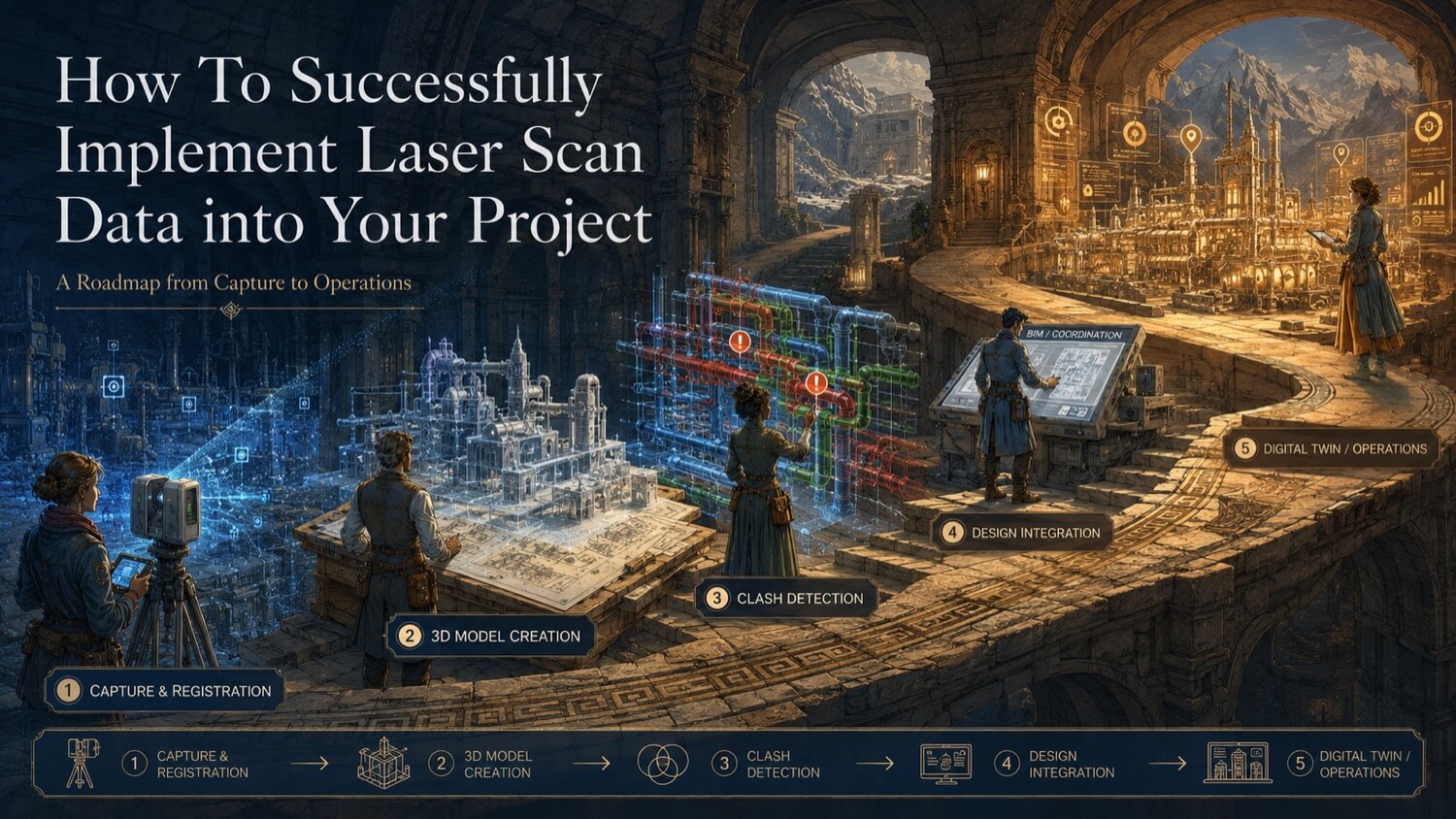
This article is a practical guide to preventing that outcome. It covers the five implementation stages, the software decisions you need to make, the workflow changes that will be required, and the team preparation steps that determine whether your scan data becomes a productive project tool or an underused archive.
Before the Data Arrives , Implementation Planning
The most effective implementation planning happens before scan day, not after data delivery. Three decisions should be made during scope definition:
Decision 1 , Who will use the data, and in what role?
Map out your data users by role. An implementation typically involves three categories:
- Primary users: Engineers or designers who will work directly in the point cloud or model to produce drawings, calculations, or designs
- Reference users: Project managers, construction supervisors, or operations staff who need to navigate the data visually but will not produce technical outputs from it
- Archive users: Document management or facilities teams who need to store, retrieve, and catalogue the data over the asset lifecycle
Each category has different software requirements, training needs, and file format preferences. Identifying them early allows you to specify deliverables that match all needs from a single capture.
Decision 2 , What software will be used?
This question has a straightforward test: before the scan data is delivered, confirm that at least one person in each user group can open and navigate the delivery format on their standard work computer.
Common software environments and compatible formats:
| Software Environment | Compatible Point Cloud Format | Notes |
|---|---|---|
| Autodesk AutoCAD / Civil 3D | RCP/RCS (via ReCap) | Requires Autodesk ReCap for conversion |
| Autodesk Revit | RCP/RCS linked | Native point cloud link workflow |
| Bentley MicroStation / OpenBuildings | POD / E57 | Check version compatibility |
| AVEVA / Hexagon plant design | PCG / E57 / RWX | Pipeline and plant-specific formats |
| FARO SCENE | FLS, E57 | Native FARO workflow |
| Leica Cyclone | BLK, PTG, E57 | Leica ecosystem |
| CloudCompare (free) | E57, LAS, LAZ, PCD | General-purpose, no engineering tools |
| Autodesk ReCap (free viewer) | RCP/RCS | Navigation only, no design tools |
Confirm your software environment with GDS before the scan begins so the delivery format is specified correctly. Changing format after delivery adds unnecessary conversion steps.
Decision 3 , Where will the data live?
Point cloud files are large , a full facility scan may range from 5 GB to over 100 GB depending on size and density. Standard email or personal drives are not appropriate storage or distribution mechanisms.
Plan your data storage before delivery: - A network-accessible shared drive with adequate storage allocation and defined access permissions - Organised folder structure: `/Project Number/Scan Data/[Point Cloud / Drawings / Models] / [Revisions]` - A named custodian responsible for managing access, versioning, and retention
The Five Implementation Stages
Stage 1 , Receive and Verify the Data
When the deliverable package arrives, confirm that it matches the agreed scope before using it for downstream decisions. The verification steps are covered in detail in Article 35, but in summary:
- Open every file and confirm it opens in your intended software
- Confirm the coordinate system matches what was agreed and that the data sits in the correct position relative to any existing project coordinate reference
- Spot-check coverage against the agreed scan scope , is all intended area present in the data?
- Verify file naming conventions are consistent with your document management requirements
If verification identifies problems, raise them with GDS within the review window. Do not proceed with design work from unverified data.
Stage 2 , Set Up the File Environment
Before distributing data to users, configure the storage environment:
- Place the master copy of all delivered files in the designated archive location with read-only permissions
- Create working copies in the project working folder for active users , work from working copies, never from the archive master
- Apply version numbering to the working copies that corresponds to the GDS delivery revision (e.g., `R1_Registered_PointCloud_Rev01`)
- Document the coordinate system, datum, and any site-to-grid transformations in a project data management register
Stage 3 , Distribute to Users
Distribute to users based on role and format need:
- Engineering / design users: Full point cloud in native project format, plus any model or drawing deliverables. Provide format conversion support if users have not worked with point clouds before.
- Reference users: Simplified deliverables are appropriate , a 3D PDF, a lightweight viewer file (e.g., Autodesk ReCap viewer), or 2D PDF drawings. Not all reference users need to navigate the full density point cloud.
- Document management / archive: All delivery formats, filed under the asset record with metadata (project number, scan date, scope, coordinate system, GDS project reference).
Provide a brief orientation session for any team members receiving scan data for the first time. A 20-minute walkthrough of how to navigate the point cloud, what the data shows, and what it does not show prevents weeks of confusion downstream.
Stage 4 , Integrate into the Engineering or Project Workflow
This is the stage where most implementation effort is concentrated, and where the most value is generated.
For engineering and design workflows: Link the point cloud to the CAD or BIM environment. In Revit, this is done via Insert > Link Point Cloud; in AutoCAD, via the Attach tool in the Point Cloud tab. Once linked, the point cloud becomes a spatial reference that the design model is built against , the designer fits new elements to the existing geometry captured in the scan rather than relying on paper drawings or manual measurements.
Practical tips for effective point cloud use in a design environment: - Set the point cloud display to elevation-coloured or intensity-coloured mode for visual clarity , true-colour display on large clouds can slow navigation - Work in cross-section views clipped to the relevant area rather than navigating the full cloud - Use snapping tools to pick points directly from the cloud for dimensional reference , do not manually type dimensions from the point cloud - Establish a named working coordinate system within the CAD environment that matches the scan coordinate system; do not work in world zero if the scan is geospatially positioned
For construction and site management: Provide site supervisors with a lightweight navigation tool (tablet-based viewer, PDF plan derived from the scan, or a printed DWG) that allows them to reference the as-built condition. For active construction sites where conditions change rapidly, define the scope boundary of the scan and be explicit about what the scan does not cover (areas excluded from scope, surfaces occluded during scanning, post-scan modifications).
For facility operations: Configure the point cloud or model in the facilities management platform or link it to asset records in the CMMS. This step typically requires format conversion and may benefit from GDS guidance on platform-specific integration.
Stage 5 , Produce Outputs from the Data
The implementation is complete when the data is producing the outputs that justified commissioning the scan in the first place: engineering drawings, conflict checks, quantity takeoffs, fabrication models, BIM models, or compliance documentation.
Track which outputs have been produced, which are in progress, and which are planned. This creates an evidence record of data use that is useful for demonstrating ROI when future scan investments are proposed internally , see Article 39 for guidance on building internal support.
Common Implementation Mistakes and How to Avoid Them
| Mistake | Consequence | Prevention |
|---|---|---|
| No pre-delivery software check | Data delivered in format nobody can open | Confirm software before specifying format |
| Working from archive master files | Risk of overwriting original data | Create working copies before distributing |
| No coordinate system documentation | Data cannot be integrated into project model | Document datum and transformation at delivery |
| Sending point cloud files via email | Transfer failure; large files corrupt or time out | Use secure file transfer or shared network path |
| No user orientation for first-time recipients | Data sits unused while users try to figure out the software | Schedule 20-minute orientation at data handover |
| No data custodian assigned | Files become inaccessible or overwritten | Assign named custodian at project initiation |
Quick Facts
Continue Reading
The next best article depends on where you are in the project. These suggested reads connect this topic to the next practical decision your team is likely to face.
FAQ
What software do I need to use laser scan data?
At minimum, a point cloud viewer is usually required. Free or low-cost options may be available depending on your file format and licensing environment, including Autodesk ReCap workflows for RCP/RCS files and CloudCompare for common open formats such as E57, LAS, and LAZ. For design and engineering work, a CAD or BIM platform with point cloud integration is required, such as Autodesk AutoCAD, Revit, Bentley MicroStation, or plant-specific platforms like AVEVA. GDS recommends confirming your software environment before specifying delivery format.
How do I load a point cloud into Revit or AutoCAD?
In Revit: Insert tab → Link Point Cloud → navigate to your RCP file. The point cloud will attach to the project and appear in all relevant views. In AutoCAD: Point Cloud tab (if active) → Attach → select your RCP or E57 file. If E57 format, you may need to convert to RCP via Autodesk ReCap first. GDS can provide format-specific guidance as part of deliverable handover.
What if my team has never used scan data before?
A short orientation session can help users understand how to navigate the point cloud, take measurements, clip to a cross-section, and understand what the data does and does not show. GDS can provide guidance when it is included in the project scope. Adoption speed depends on the user's software experience, file size, hardware, and intended workflow.
Can contractors and subconsultants access the scan data?
Yes, subject to your project data sharing protocols. Scan data can be shared with external parties via secure file transfer. For reference use, PDF drawings, lightweight 3D viewers, or trimmed point cloud extracts are often more appropriate than sharing the full registered point cloud. Confirm data sharing and intellectual property terms in your project documentation.
Connect this resource to the right GDS workflow
These resource pages are intended to help teams make better planning decisions before a scope is finalized. GDS can help confirm whether the work should start with 3D laser scanning, continue into 3D modeling, require reverse engineering, or benefit from early consulting before budget, schedule, and deliverables are locked in.
GDS lists nationwide service coverage on its locations page, including posted major metropolitan areas such as Houston, Dallas, San Antonio, Austin, Los Angeles, San Diego, San Jose, Long Beach, Fort Worth, Irvine, Riverside, New Orleans, Baton Rouge, Shreveport, Las Vegas, and Beverly Hills.