

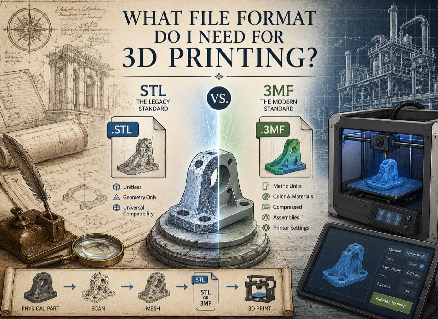
3D printing (additive manufacturing) slicing software requires tessellated mesh files , formats that define the outer surface of a part as a collection of flat triangular faces. The two primary formats are STL (.stl) and 3MF (.3mf). STEP files, Parasolid, and native CAD formats cannot be directly sliced by most additive manufacturing software and must be converted to mesh before printing.
Additive Manufacturing Requires Tessellated Mesh Files
Unlike CNC machining, which uses analytical surface definitions to compute smooth cutting paths, 3D printing slicers work layer by layer: the slicer calculates the cross-section of the 3D model at each layer height and generates the deposition path for that layer. This layer-slice operation works efficiently on triangulated mesh geometry , the flat triangular faces provide the slicer with a simple, fast boundary to intersect.
For most professional industrial 3D printing technologies , FDM, SLA, SLS, DMLS, HP MJF, EOS , STL or 3MF are the standard input formats. STEP geometry must be exported from CAD software as a mesh before submission.
STL , The Legacy Standard
STL is the oldest and most universally accepted 3D printing format. Nearly every desktop and industrial 3D printer accepts STL files. Its key characteristics:
- Unitless: No metric or imperial unit is embedded in the file. Import scale depends entirely on the slicer's unit setting.
- Geometry only: No color, no material, no layer configuration, no assembly structure.
- Simple structure: A flat list of triangle definitions. Human-readable in ASCII format; compact in binary format.
- Universal compatibility: Accepted by every slicer without exception.
Primary risk: Unit mismatch on import. An STL modeled in millimetres imported into an inch-configured slicer produces a part 25.4× the intended size. Always confirm slicer unit settings before submitting to print.
3MF , The Modern Professional Standard
The 3MF (3D Manufacturing Format) standard, developed by the 3MF Consortium and supported by Microsoft, Autodesk, HP, Stratasys, EOS, and others, addresses every structural limitation of STL:
| Feature | STL | 3MF |
|---|---|---|
| Units | None (unitless) | Explicit metric (mm) |
| Color support | None | Full RGB per face or texture |
| Material data | None | Material properties embedded |
| Compression | None | XML in ZIP container (60 to 80% smaller) |
| Watertight enforcement | Not enforced | Required by spec |
| Multi-component assemblies | Not supported | Fully supported |
| Printer configuration | None | Printer settings embedded |
3MF is the preferred format for professional additive manufacturing workflows, particularly for:
- HP Multi Jet Fusion (MJF): Expects 3MF for color and voxel-level material control
- Stratasys PolyJet / J Series: 3MF for multi-material assignments
- Metal DMLS/SLM: 3MF for build parameters and support strategies
- Full-color binder jetting (Stratasys, 3D Systems): 3MF for CMYK color mapping
STL vs. 3MF: Which Should You Use?
| Use Scenario | Recommended Format |
|---|---|
| Desktop FDM printing (Bambu, Prusa, Ultimaker) | STL or 3MF (both widely supported) |
| Professional SLS / DMLS powder bed fusion | 3MF preferred |
| HP Multi Jet Fusion | 3MF , color and density control |
| Full-color polyjet / binder jetting | 3MF , required for color data |
| Service bureau submission (simple single material) | STL (universal fallback) |
| Service bureau submission (professional) | 3MF (preferred) |
Rule of thumb: Use 3MF for any professional industrial printer. Use STL only when the service bureau or printer specifically requires it.
The Watertight Requirement
Both STL and 3MF files must be watertight (manifold) for successful slicing:
- Every edge shared by exactly two triangular faces
- No open boundaries, no gaps, no T-junctions
- No self-intersecting faces
A non-watertight mesh causes slicing failures, incorrect infill, or print errors. GDS performs automated non-manifold detection and mesh healing on every additive manufacturing deliverable, followed by visual confirmation of watertight closure before file handoff.
What GDS Delivers for Additive Manufacturing
When GDS reverse engineers a physical component for additive manufacturing reproduction:
| Deliverable | Description |
|---|---|
| High-resolution STL | Watertight, binary format with unit documentation |
| 3MF package | Explicit metric units, printer-compatible settings |
| Mesh quality report | Confirms zero non-manifold edges, watertight status |
| Unit confirmation note | Explicit import scale confirmation for service bureau |
GDS also advises on print orientation, support strategy, and material selection for the specific printer technology the client is using , reducing iteration cycles between file delivery and successful print.
Quick Facts
Continue Reading
The next best article depends on where you are in the project. These suggested reads connect this topic to the next practical decision your team is likely to face.
FAQ
Can I send a STEP file to a 3D printer?
Most slicing software cannot directly process STEP files. STEP geometry must first be exported from CAD software as a high-resolution STL or 3MF mesh before it can be sliced and printed. GDS can include this conversion in additive manufacturing deliverable packages when it is part of the requested scope.
What resolution should my STL file be for industrial 3D printing?
For industrial printing with features smaller than 2 mm or curved surfaces requiring smooth appearance, export STL at a chord deviation of 0.01 to 0.05 mm and angular tolerance of 0.5 to 1°. This produces a high-resolution mesh with file sizes typically between 10 to 100 MB. GDS configures export resolution based on the client's printer technology and minimum feature size.
Why did my 3D-printed part come out the wrong size?
The most common cause is a unit mismatch on STL import. STL contains no unit information , if your model was built in millimetres and the slicer interpreted the file in inches, the printed part will be 25.4× the intended size. GDS can include explicit unit documentation with STL delivery. Always verify the unit setting in your slicer before submitting to print.
Connect this article to the right GDS workflow
Most physical-to-digital projects touch more than one service. GDS can help determine whether the right starting point is 3D laser scanning, 3D modeling, reverse engineering, or consulting before scope, pricing, schedule, and deliverables are finalized.
GDS lists nationwide coverage from its locations page, including posted major metropolitan areas such as Houston, Dallas, San Antonio, Austin, Los Angeles, San Diego, San Jose, Long Beach, Fort Worth, Irvine, Riverside, New Orleans, Baton Rouge, Shreveport, Las Vegas, and Beverly Hills.
Need a Print-Ready Mesh from a Physical Part?
GDS delivers watertight STL and 3MF files from any physical object , with mesh quality reports and unit documentation, ready for professional additive manufacturing submission.