

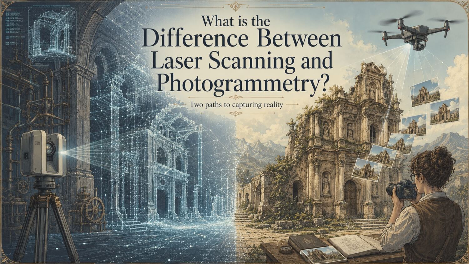
Laser scanning and photogrammetry are both methods for capturing the three-dimensional geometry of physical objects and environments. They can look similar from the outside because both may produce point clouds, textured meshes, or visual records. The difference is how the data is created, how dependable it is for engineering decisions, and what type of deliverable the project actually needs.
Selecting the wrong method can lead to missing geometry, unusable data, rework, or unnecessary cost. The safer question is not “which technology is better?” It is “which capture method fits the decision we need to make?”
Global Design Solutions helps clients connect capture method to final deliverable through 3D laser scanning, 3D modeling, reverse engineering, and consulting. For Article 21, the goal is to explain the tradeoff honestly without implying that a broad educational article defines project accuracy, inspection method, or compliance deliverables.
Two Fundamentally Different Physical Measurement Principles
Laser scanning measures geometry by physics: a laser pulse (or structured light fringe) is emitted, strikes the physical surface, and returns to the sensor. The instrument calculates the precise 3D coordinate of the surface point from the physics of light travel, either time-of-flight (for LiDAR) or triangulation geometry (for structured light). The measurement is direct, physical, and independent of surface appearance or lighting conditions.
Photogrammetry measures geometry by mathematics: a series of overlapping photographs is taken from multiple positions, and computer vision algorithms calculate 3D surface coordinates by finding matching features in adjacent images and triangulating their positions. The measurement is indirect, derived from pixel matching, and is dependent on surface texture, lighting, and image resolution.
How Laser Scanning Works
Terrestrial LiDAR scanners rotate a laser beam across a large field of view and record high-density X, Y, Z coordinate measurements of visible surfaces. Each scan position captures the geometry that the instrument can see from that setup. Adjacent scan positions are then registered, or aligned, into a coordinated dataset.
Structured-light and handheld scanners are often used for smaller components, tighter access, or reverse engineering workflows. These tools can support tighter tolerances than large-area facility scanning when the part geometry, surface condition, equipment setup, and project scope are appropriate.
Key property: Laser scanning measures visible physical surfaces directly. It does not rely on photographic texture the same way photogrammetry does, although access, line-of-sight, surface finish, control method, and deliverable requirements still matter.
How Photogrammetry Works
Photogrammetry begins with a series of overlapping photographs, typically 60 to 80% overlap between adjacent images, captured from a drone (aerial photogrammetry) or on foot (close-range photogrammetry). Software such as Agisoft Metashape or RealityCapture performs:
1. Feature detection: Identifying visually distinctive pixel patterns in each image 2. Feature matching: Finding the same physical feature in multiple overlapping images 3. Bundle adjustment: Computing the camera position and orientation for each photo and the 3D coordinate of each matched feature simultaneously
The output is a dense point cloud derived from photographic pixel data, and a photorealistic textured mesh.
Key property: Photogrammetry requires surface texture and contrast. Featureless flat surfaces, transparent materials, and highly reflective surfaces confuse feature-matching algorithms and produce data gaps.
Head-to-Head Comparison
| Property | Laser Scanning | Photogrammetry |
|---|---|---|
| Measurement principle | Direct active measurement of visible surfaces | Indirect reconstruction from overlapping photographs |
| Facility-scale use | Strong fit for interiors, MEP, structural steel, equipment, tie-ins, and as-built modeling | Strong fit for exterior context, terrain, roofs, and textured visual documentation |
| Part-scale use | Often used for reverse engineering, inspection support, and scan-to-CAD workflows | Useful for textured objects and visual reconstruction, but not a universal substitute for scan-to-CAD work |
| Textureless surfaces | Generally stronger because measurement is not based on image feature matching | Can struggle when surfaces lack visible features or contrast |
| Reflective or transparent surfaces | May require surface preparation, scan strategy changes, or alternate measurement methods | Can struggle with glare, transparency, and overexposure |
| Lighting dependency | Less dependent on ambient light for geometry capture | Highly dependent on image quality, lighting, overlap, and camera settings |
| Primary output | Registered point cloud and downstream CAD/BIM/modeling deliverables when scoped | Dense point cloud, textured mesh, orthomosaic, or visual context deliverable |
| Best question to ask | Do we need reliable geometry for engineering, modeling, fit-up, or verification? | Do we need broad visual context, exterior coverage, or photorealistic documentation? |
When Laser Scanning Is the Correct Choice
- Industrial facility documentation: Complex piping, structural steel, equipment pads, tanks, and mechanical rooms usually need direct surface measurement because photographic reconstruction can miss geometry in dense or shadowed areas.
- Scan-to-model and as-built work: If the deliverable is a point cloud, Revit model, CAD reference, or installation planning dataset, 3D laser scanning is typically the more defensible capture method.
- Precision component reverse engineering: For replacement parts, wear analysis, or scan-to-CAD reconstruction, a controlled scanning workflow tied to reverse engineering and 3D modeling deliverables is usually more appropriate than general-purpose photogrammetry.
- Dark, enclosed, or visually repetitive spaces: Laser scanning is less dependent on ambient lighting and surface texture, although line-of-sight and setup planning are still important.
- When tolerance language matters: Accuracy, validation method, coordinate control, and reporting requirements should be defined in the proposal. This article does not claim that GDS performs every scan to a specific third-party, aerospace, or client compliance standard unless those requirements are expressly scoped.
When Photogrammetry Is the Correct Choice
- Large outdoor areas: Aerial photogrammetry can be useful for terrain, roof context, construction progress, quarries, laydown yards, and exterior site visualization when the required tolerance fits that method.
- Textured heritage and architectural subjects: Highly textured surfaces such as stone facades, decorative plasterwork, and archaeological features can reconstruct well because the texture provides many matching points.
- Photorealistic visualization: Photogrammetry can produce textured meshes that are useful for stakeholder communication, visual context, and presentation work.
- Early reconnaissance: Low-cost photographic capture may help teams understand a site before committing to a formal consulting, scanning, or modeling scope.
Hybrid Workflows: When Both Methods May Make Sense
Some projects benefit from combining direct measurement with photographic context. A practical hybrid workflow might use terrestrial laser scanning for the interior geometry that supports design, modeling, or fit-up, while using aerial imagery or photogrammetry for exterior context, roof plans, surrounding terrain, or stakeholder communication.
That does not mean every project needs both. GDS can help define when a hybrid approach is useful, what should be captured by each method, and how the resulting data should be organized for downstream use. The scope should clearly state whether the final deliverable is a point cloud, mesh, CAD model, Revit model, site context package, or a combination of these.
Quick Facts
Continue Reading
The next best article depends on where you are in the project. These suggested reads connect this topic to the next practical decision your team is likely to face.
FAQ
Is photogrammetry accurate enough for industrial engineering?
Photogrammetry can be useful for visual context, terrain, exterior documentation, and textured subjects. For dense industrial interiors, pipe tie-ins, equipment layout, and scan-to-model work, terrestrial laser scanning is usually the safer choice because it captures direct 3D measurements. Final accuracy expectations should be confirmed in the project scope, equipment selection, and deliverable requirements.
Can drone photogrammetry replace terrestrial LiDAR for facility scanning?
Drone photogrammetry is not a direct replacement for terrestrial laser scanning inside facilities. It is strongest for exterior site context, roofs, terrain, and large outdoor areas. Interior process areas, piping, structural steel, and mechanical rooms typically require terrestrial scanning or another direct measurement workflow.
Does GDS offer photogrammetry services?
GDS primarily supports engineering capture through 3D laser scanning, 3D modeling, reverse engineering, and consulting. When aerial or photogrammetric context is useful, GDS can discuss a hybrid workflow or coordinate the appropriate capture approach during project scoping.
How GDS Helps You Choose the Right Capture Workflow
Choosing between laser scanning and photogrammetry is not just a technology decision. It affects budget, schedule, engineering confidence, and the usefulness of the final deliverable. GDS connects the capture method to the project outcome so clients do not pay for the wrong type of data.
Posted GDS service areas include: Houston, Dallas, San Antonio, Austin, Los Angeles, San Diego, San Jose, Long Beach, Fort Worth, Irvine, Riverside, New Orleans, Baton Rouge, Shreveport, Las Vegas, and Beverly Hills. GDS also lists offices in Torrance, California and Houston, Texas.
Not Sure Which Method Your Project Needs?
GDS can review your project goal, site conditions, deliverable requirements, and accuracy expectations before recommending laser scanning, photogrammetry, a hybrid workflow, or a different measurement approach.