


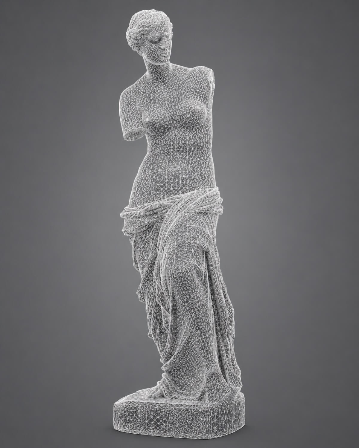
A mesh file represents the outer surface of a three-dimensional object as a continuous network of flat polygons, almost always triangles. Rather than describing geometry using mathematically defined curves and solid boundaries (as a parametric CAD model does), a mesh defines the object's boundary skin using three fundamental topological elements: vertices, edges, and faces.
Understanding the distinction between a mesh and a parametric solid model is one of the most important concepts in industrial digitization. These are not interchangeable formats, they serve fundamentally different purposes, and selecting the wrong type for a downstream manufacturing process can produce costly errors.
How GDS Can Help
Most physical-to-digital projects touch more than one discipline. GDS can support the workflow from field capture through usable engineering deliverables with 3D laser scanning, 3D modeling, reverse engineering, and consulting.
GDS lists coverage across major metropolitan areas including Houston, Dallas, San Antonio, Austin, Los Angeles, San Diego, San Jose, Long Beach, Fort Worth, Irvine, Riverside, New Orleans, Baton Rouge, Shreveport, Las Vegas, and Beverly Hills. See the current GDS locations page for posted service areas.
Scope note: Specific tolerances, certification requirements, deliverables, schedules, reports, site control, and acceptance criteria should be defined in the quote, proposal, or statement of work for the individual project.
Anatomy of a Tessellated Surface
A mesh is built from three primitive elements stacked into a hierarchy:
| Element | Definition |
|---|---|
| Vertex | A single discrete coordinate point in 3D space (X, Y, Z) |
| Edge | A straight line segment connecting exactly two vertices |
| Face | A flat triangular surface bounded by three edges |
Every surface on a mesh object, no matter how curved it appears, is actually a collection of flat triangular faces. A smooth-looking cylinder in a mesh file is not mathematically smooth; it is a faceted approximation made up of hundreds or thousands of flat triangles arranged around a central axis. The higher the triangle count (mesh resolution), the closer the approximation approaches true cylindrical form.
This approximation is the fundamental limitation of mesh geometry and the reason why mesh files cannot replace parametric solid models in precision manufacturing workflows.
How a Mesh Is Created from Scan Data
When GDS completes the registration and quality control of a raw point cloud, the next step for many project types is polygonization: the algorithmic process of converting a cloud of disconnected coordinates into a continuous surface mesh.
The meshing algorithm examines the spatial density and distribution of point cloud coordinates and draws triangular faces between adjacent points. The result is a watertight mesh shell that captures the physical surface of the scanned object with high fidelity, preserving casting textures, weld profiles, corrosion pockets, and as-built dimensional deviations exactly as they existed at the moment of scanning.
Mesh resolution is controlled by the triangle count:
- Low-resolution mesh: Fewer, larger triangles. Smaller file size. Visible faceting on curved surfaces. Appropriate for large-scale facility models used in BIM coordination.
- High-resolution mesh: Millions of tiny triangles. Large file size. Near-smooth curved surfaces. Required for precision reverse engineering and deviation analysis.
What a Mesh Can and Cannot Do
| Capability | Mesh | Parametric CAD Solid |
|---|---|---|
| Represent real-world as-built geometry | Yes | Requires modeling effort |
| 3D printing (slicing) | Yes , native format | Requires export to mesh |
| CNC machining toolpaths | No , faceted surfaces cause chatter | Yes , mathematically smooth |
| Dimensional tolerancing and GD&T | No | Yes |
| Editable features (hole diameter, wall thickness) | Very difficult | Yes , parametric |
| Deviation analysis vs. nominal CAD | Yes , as inspection reference | Yes , as nominal target |
| FEA structural simulation | Limited (surface only) | Yes , solid volumes |
The mesh is the correct format for 3D printing, visual inspection, forensic analysis, and as the reference surface in scan-to-CAD deviation analysis. It is not the correct format for CNC machining, engineering drawing generation, or design modification.
Mesh Quality: Watertight vs. Non-Manifold Geometry
Not all mesh files are usable. A mesh must meet specific quality standards to function correctly in downstream software:
Watertight (Manifold) Mesh: Every edge is shared by exactly two triangular faces. There are no gaps, holes, or open boundaries. The mesh clearly defines an "inside" and an "outside" of the object. 3D printing slicers, deviation analysis software, and rendering engines all require watertight meshes.
Non-Manifold Geometry: Defects including open edges (missing faces), T-junctions (three faces sharing one edge), and self-intersecting faces. Non-manifold meshes cause slicing failures in 3D printing, incorrect deviation calculations, and rendering artifacts.
GDS mesh processing includes automated non-manifold detection and repair using professional-grade tools (Geomagic Wrap, MeshLab), followed by visual inspection to confirm watertight closure before delivery.
Common Mesh File Formats
| Format | Extension | Key Characteristics |
|---|---|---|
| STL | .stl | Universal 3D printing standard; unitless; geometry only |
| OBJ | .obj | Includes UV texture coordinates and material references |
| PLY | .ply | Open format; stores color, intensity, and custom data per vertex |
| 3MF | .3mf | Modern XML-based printing standard; includes units and material data |
| FBX | .fbx | Rich animation and rendering format; common in visualization |
For industrial reverse engineering and 3D printing deliverables, GDS defaults to STL or 3MF. For visualization and client review, OBJ with texture mapping provides the most photorealistic result.
Where Mesh Files Fit in the Engineering Pipeline
The mesh occupies a specific, non-replaceable position between raw point cloud data and finished parametric CAD:
Point Cloud → Mesh → Parametric CAD
The mesh serves as the 3D tracing template over which a CAD engineer rebuilds the object feature-by-feature. It provides the dimensional accuracy of the physical object without the parametric intelligence of an editable solid. This is why mesh-only deliverables are appropriate for forensic documentation and 3D printing but insufficient for CNC machining programs or engineering drawing packages.
Quick Facts
Continue Reading
The next best article depends on where you are in the project. These suggested reads connect this topic to the next practical decision your team is likely to face.
FAQ
Is a mesh file the same as a CAD file?
No. A mesh file defines an object's outer surface as a collection of flat triangular faces. A CAD file defines geometry using exact mathematical curves, solid boundaries, and editable parametric features. Mesh files are used for 3D printing and visualization; parametric CAD files (STEP, Parasolid) are required for CNC machining and design modification.
Can a mesh file be converted to a STEP file?
Not automatically with reliable results. Converting a mesh to a parametric STEP file requires a skilled engineer to trace new parametric features over the mesh geometry, a process called reverse engineering. Automated mesh-to-STEP converters exist but produce poor-quality, faceted solids that are not suitable for CNC machining.
What is a watertight mesh and why does it matter?
A watertight mesh has no gaps, holes, or open edges, every edge is shared by exactly two triangular faces. Watertight geometry is required by 3D printing slicers to calculate the solid interior of a part. Non-watertight meshes cause print failures, incorrect material volume estimates, and slicing errors.
Need a Manufacturing-Ready Mesh or STEP File?
GDS delivers watertight mesh files for 3D printing and fully verified STEP AP242 solids for CNC machining , from any physical object, no drawings required.