

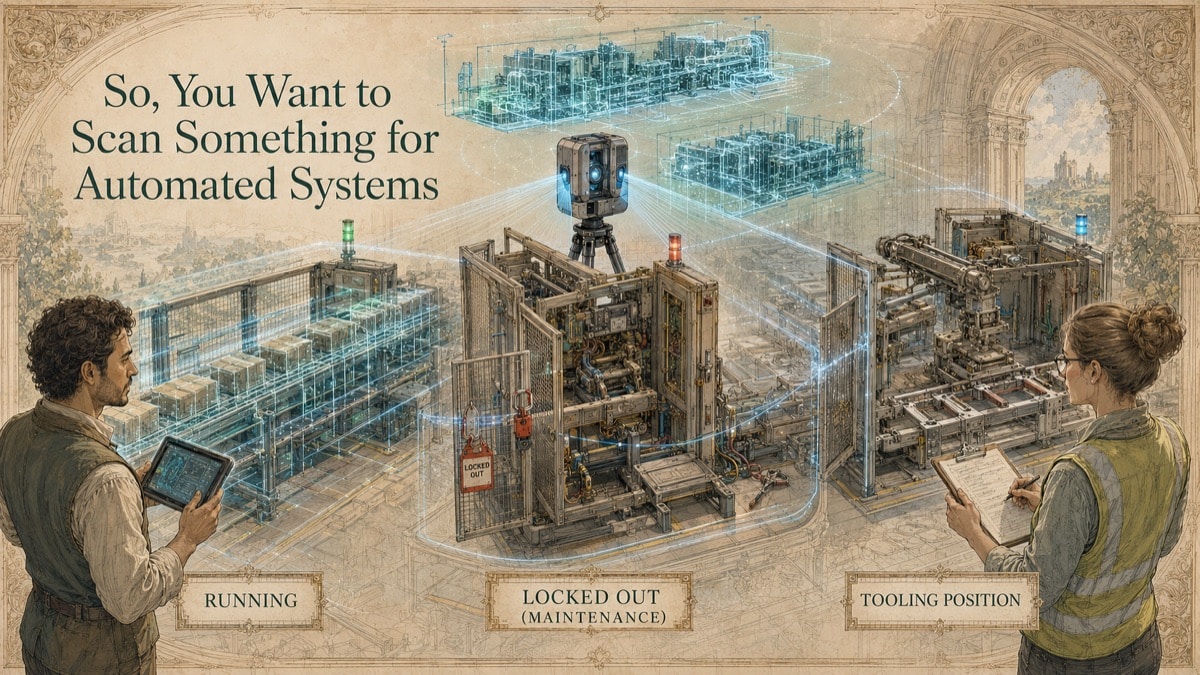
A manufacturer wants to replace a conveyor and add an automated inspection station without stopping production longer than necessary. The drawings show a clean route. The floor has enough room on paper. But the actual line includes added guarding, undocumented electrical cabinets, shifted machine bases, temporary utilities that became permanent, and moving equipment that only occupies its full envelope during maintenance. The problem is not whether the new system is a good idea. The problem is that the team is designing around a version of the facility that no longer exists.
Scanning an automated system creates a controlled spatial baseline for integration decisions. It can support layout, retrofit planning, clearance review, virtual fit-up, equipment documentation, and scan-derived CAD. It should also clearly record the system state at the time of capture, because automated lines are not static objects.
Key Takeaway
Automated-system scanning is most useful when it defines equipment state, access, coordinates, critical interfaces, and the downstream deliverable before capture. A scan supports spatial integration, but it does not replace controls, safety, process, or engineering validation.
The Automation Retrofit Problem
Automated systems combine fixed equipment, moving assemblies, conveyors, utilities, controls, guarding, sensors, access zones, operators, and maintenance paths. A model that captures only the machines may miss the conditions that actually determine whether new equipment can be installed.
The risk is higher in brownfield facilities. Existing lines are often modified across years of urgent fixes and production improvements. Cabinets are relocated. Brackets are welded in place. Conduit is field-routed. Guards are altered. Temporary bypasses become permanent. Unless the scan scope is aligned to the integration decision, the final dataset may look impressive while still missing the constraints that matter.
This is why GDS treats automated-system scanning as a planning exercise first and a field activity second. The correct question is not, “Can we scan the line?” The correct question is, “What integration, retrofit, or verification decision must the scan support?”
Define the System State Before Capture
Automation lines move. Conveyors may be empty, loaded, jammed, or in accumulation. Lift tables may be home, extended, or in service position. Gates, guarding, doors, cylinders, robots, fixtures, tooling, and access panels may exist in multiple states. A scan captures a moment in time unless those states are deliberately managed.
| System State Decision | Why It Matters | Risk if Undefined |
|---|---|---|
| Running, idle, or locked out | Determines safety, movement, vibration, and access | Geometry is blurred, blocked, or unsafe to capture |
| Loaded or empty conveyor | Changes clearance and transfer assumptions | New equipment is designed around the wrong operating condition |
| Guards open, closed, or removed | Changes maintenance and access envelopes | Maintenance clearance is missed or overstated |
| Tooling home or extended | Defines collision and service envelopes | Model represents only one usable position |
| Plant, machine, or local coordinates | Controls downstream placement | Integrator cannot place the data consistently |
Table accessibility note: Each row identifies a system-state decision, why it matters, and the risk created when that decision is not defined.
The Seven-Step Automated-System Capture Workflow
Step 1 - Define the engineering outcome
Identify the change being planned: conveyor replacement, robot integration, line expansion, equipment swap, clearance review, virtual fit-up, documentation, or digital twin baseline.
Step 2 - Establish safety and access conditions
Confirm orientation, escorts, lockout/tagout boundaries, scanner locations, elevated access, production windows, and any areas that cannot be accessed or disturbed.
Step 3 - Approve the system state
Document whether machines are running, idle, empty, loaded, open, closed, guarded, locked out, or captured in multiple positions. The deliverable should state the configuration clearly.
Step 4 - Capture critical and contextual geometry
Capture critical interfaces at the required level of confidence and enough surrounding context to understand access, clearances, routes, adjacent equipment, and maintenance needs.
Step 5 - Register and control coordinates
Align scans using an approved method and document the coordinate basis, units, origin, axes, and any transformations into plant or machine coordinates.
Step 6 - Create authorized derivatives
Produce point clouds, meshes, drawings, sections, STEP/IGES exchange geometry, layout models, or deviation reports according to the approved use.
Step 7 - Verify delivery before reliance
Check coverage, scale, file health, layer naming, coordinate placement, and critical dimensions. When possible, test a representative file in the target software.
Deliverables for Integrators, Engineers, and Operations
No single file works for every automation stakeholder. Integrators may need simplified solids or collision context. Mechanical engineers may need equipment envelopes, anchor locations, and clearances. Electrical teams may need cabinet, tray, conduit, and penetration positions. Operations may need access and maintenance space. Safety teams may need guarding and personnel envelope context.
A registered point cloud is often the best measurement record. A mesh can represent measured surface context. STEP or IGES may support CAD exchange when geometry is reconstructed or simplified. DWG/DXF may be best for plan layouts, equipment footprints, and sections. Deviation maps may support comparison to a nominal vendor model when suitable surfaces and acceptance criteria are available.
The deliverable should state whether geometry is measured, simplified, reconstructed, nominal, or excluded. That status protects the downstream team from assuming a coordination model is a fabrication model.
What the Scan Does Not Prove
A scan can support spatial integration, but it does not prove the automated system will perform. Throughput, controls logic, functional safety, electrical loading, guarding compliance, process capability, vibration, structural support, and machine performance require separate review by the responsible experts.
The scan also cannot measure concealed utilities, internal machine components, or hidden structural conditions unless those elements are exposed or provided from reliable records. When concealed or nominal geometry is added for coordination, it should be labeled as such.
How GDS Helps Teams Avoid Over-Scanning and Under-Scoping
The most expensive automation data mistake is not always scanning too much. It is scanning without knowing what the team will do with the result. GDS helps define decision-critical interfaces, file outputs, operating-state requirements, and review steps so the project receives usable data rather than raw volume.
System-State Capture Map
Mark the operating states that affect the planned change. The result helps identify whether one capture state is enough.
Quick Facts
Continue Reading
The next best article depends on where you are in the project. These suggested reads connect this topic to the next practical decision your team is likely to face.
Frequently Asked Questions
Can scanning be performed while the automated line is operating?
Sometimes, but feasibility depends on safety rules, movement, vibration, traffic, access, and whether changing geometry would compromise the intended dataset.
Can GDS model concealed utilities or internal machine components?
Only visible and measurable geometry is scan-derived. Concealed information can be added from reliable records or nominal models when authorized and clearly identified as non-measured.
Do we need both a point cloud and a CAD model?
Often, yes. The point cloud preserves measurement evidence, while CAD or simplified geometry supports design, coordination, and integration.
Can a scan verify a vendor’s nominal equipment model?
Yes, when suitable measured surfaces and nominal CAD are available. The report should state alignment method, tolerance bands, exclusions, and review purpose.
What is the biggest automation-scanning scope mistake?
The biggest mistake is failing to define the system state, coordinate basis, and critical interfaces before capture.
Connect this article to the right GDS workflow
Most physical-to-digital projects touch more than one service. GDS can help determine whether the right starting point is 3D laser scanning, 3D modeling, reverse engineering, or consulting before scope, pricing, schedule, and deliverables are finalized.
GDS supports projects nationwide. Examples from the current locations page include San Diego, San Jose, Las Vegas, and Los Angeles.
Ready to Start?
Tell GDS about your asset, your goals, and your deliverable needs. GDS can scope the right scanning, modeling, and reporting for your project.