

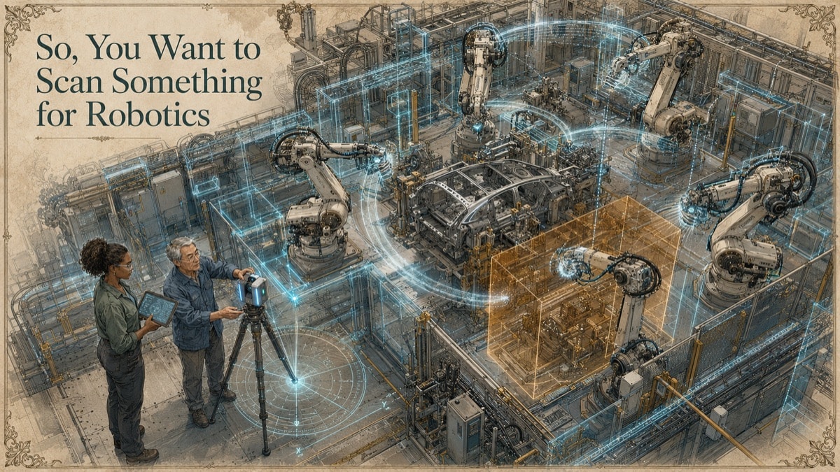
A robot integrator is asked to add a new robot into an existing production area. The CAD layout looks workable. The reach study looks reasonable. Then the team sees the real cell: a guard rail shifted during a previous project, a conveyor support that was never modeled, cable tray lower than the drawing shows, and a service clearance that only exists on paper. None of those issues are robot programming problems. They are physical-geometry problems that should have been captured before the robot layout became a commitment.
Robotics scanning is not just “making a digital copy” of a cell. It is a decision-support workflow. The purpose may be collision context, tooling design, fixture documentation, part localization, offline programming reference, retrofit planning, or scan-to-CAD comparison. Each purpose needs a different level of detail, coordinate strategy, and deliverable.
Key Takeaway
Robotics scanning is most useful when capture is tied to a defined robotic decision. Geometry can support cell planning, tooling, collision context, and comparison, but it does not calibrate a robot, validate safety, or qualify a process by itself.
The Robot Cell Problem: Geometry Is Not the Same as Calibration
A scan can document the robot cell, but it does not make the robot accurate. Robot mastering, base-frame establishment, tool-center-point calibration, safety validation, and process qualification are separate activities unless expressly scoped. This distinction matters because teams often expect one dataset to answer every robotics question.
A broad scan can help the integrator understand the work envelope, guards, conveyors, columns, utilities, and surrounding constraints. A focused close-range capture may be needed for tooling faces, part nests, fixture datums, or end-effector interfaces. A simplified collision model may be more useful than a high-resolution mesh if the goal is simulation speed. A deviation report may be more useful than a pretty model if the goal is to compare a manufactured fixture against nominal CAD.
This is why GDS treats the robotics scan as a workflow tied to the downstream use. The question is not simply, “Can we scan the cell?” The better question is, “What does the robotics team need to decide, design, verify, or avoid?”
Start With the Robotic Decision
The scan scope should begin with the robotic task. For cell planning, the important geometry may include guarding, operator aisles, conveyors, machine envelopes, utilities, maintenance clearance, and equipment that could interfere with robot motion. For tooling design, the important geometry may be smaller: mating faces, pickup points, locating features, flange patterns, and clearance zones around the tool.
For inspection or repeatability, the scan may need to compare a measured object against a supplied nominal model. That comparison should state the alignment method, tolerance band, exclusions, and whether the output is a review exhibit or part of a formal inspection process.
The robot coordinate frame is also central. A useful model should be placed in a coordinate system the robotics team can interpret. That may be a robot base, a cell datum, survey control, plant coordinates, or a local project coordinate system. If that relationship is not defined, even an accurate model can be difficult to place correctly in simulation.
The Five-Phase Robotics Scan Workflow
Phase 1 - Define the robotic use case
Identify whether the scan supports layout, collision context, tooling, fixture design, inspection, offline programming support, or documentation. Name the decision owner and the software environment that will consume the deliverable.
Phase 2 - Define capture boundaries and coordinate frame
Map the critical geometry, contextual geometry, excluded areas, equipment states, and coordinate reference. Include moving equipment states when gates, cylinders, slides, conveyors, or access panels affect the usable envelope.
Phase 3 - Capture visible geometry
Plan scanner positions, targets, lighting, access, safety controls, and supplemental close-range capture where needed. Record what was visible, what was blocked, and what configuration the cell was in during capture.
Phase 4 - Build fit-for-purpose geometry
Create the authorized derivative: registered point cloud, mesh, simplified collision model, STEP/IGES exchange geometry, drawings, or a deviation report. The model should distinguish measured, simplified, reconstructed, nominal, and excluded geometry.
Phase 5 - Validate before use
Check units, origin, orientation, coverage, scale, layer naming, file opening, and representative dimensions. When the result will support design or programming decisions, review the deliverable with the robotics or integration team before release.
Match the Deliverable to the Robotic Use Case
| Robotic Use Case | Useful Deliverable | What to Confirm |
|---|---|---|
| Cell layout and reach review | Registered point cloud and simplified cell geometry | Coordinate frame, major obstructions, clearance zones, and equipment state |
| Collision context | Simplified collision model or mesh | Smallest obstacle that must remain represented and acceptable simplification |
| End-of-arm tooling | Scan-derived CAD, mesh, or interface model | Critical faces, datums, mating geometry, and design-intent treatment |
| Fixture or nest documentation | Mesh, CAD, drawings, or deviation map | Functional surfaces, repeatability features, and model status |
| Inspection support | Scan-to-nominal comparison report | Alignment method, tolerance band, excluded surfaces, and review authority |
Table accessibility note: Each row identifies the robotic use case, the likely deliverable, and the checks that should be confirmed before relying on the result.
What Can Go Wrong If the Scope Is Too Generic
The most common failure is asking for “a scan of the robot cell” without defining what the scan must support. That can produce too much background data and not enough information at the critical interface. It can also create a model that looks complete but misses thin guards, cables, tooling positions, or moving-state envelopes.
Another risk is treating a point cloud as if it were a simulation-ready model. Point clouds preserve measured evidence, but they may be heavy and inefficient for robot simulation. They often need segmentation, simplification, collision-surface development, or CAD conversion. The acceptable level of simplification should be agreed before processing begins.
A third risk is mistaking scan data for robot validation. Geometry can support planning, but it does not approve motion, safety, controls, force, speed, guarding, or process capability. Those remain the responsibility of qualified robotics, safety, controls, and process stakeholders.
How GDS Supports Robotics Projects
GDS can help define the capture scope, coordinate strategy, data hierarchy, and deliverable format before scanning begins. The outcome may be a registered point cloud for evidence, a simplified robot-cell model for context, scan-derived CAD for tooling, or comparison reporting when nominal CAD is available.
The most useful robotics deliverables are clear about status. The end user should be able to tell what was measured directly, what was modeled from the scan, what was simplified for performance, what came from nominal CAD, and what remains outside the evidence.
Robotics Decision Mapper
Choose the decision driving the project. The result identifies the geometry and responsibility boundaries that should be addressed before capture.
Quick Facts
Continue Reading
The next best article depends on where you are in the project. These suggested reads connect this topic to the next practical decision your team is likely to face.
Frequently Asked Questions
Can a scan be used directly for offline robot programming?
Sometimes, but most workflows require coordinate control and simplified collision geometry before the data is useful. Confirm units, origin, axis convention, file density, and the robot-base relationship with the robotics team.
Does scanning calibrate the robot?
No. Scanning can document geometry and support frame planning, but robot calibration, mastering, tool-center-point calibration, safety validation, and process qualification are separate activities.
Should I request a point cloud, mesh, or CAD model?
Use a point cloud to preserve measurement evidence, a mesh for measured surface context, and CAD when exchangeable design geometry is required.
What accuracy should be specified?
Specify accuracy at the feature or decision level. A gripper interface usually requires tighter control than background cell geometry.
Can GDS compare a fixture or part against nominal CAD?
Yes, when suitable measured surfaces and nominal CAD are available. The comparison should identify alignment method, tolerance band, exclusions, and reporting purpose.
Connect this article to the right GDS workflow
Most physical-to-digital projects touch more than one service. GDS can help determine whether the right starting point is 3D laser scanning, 3D modeling, reverse engineering, or consulting before scope, pricing, schedule, and deliverables are finalized.
GDS supports projects nationwide. Examples from the current locations page include Houston, Dallas, Austin, and Fort Worth.
Ready to Start?
Tell GDS about your asset, your goals, and your deliverable needs. GDS can scope the right scanning, modeling, and reporting for your project.