

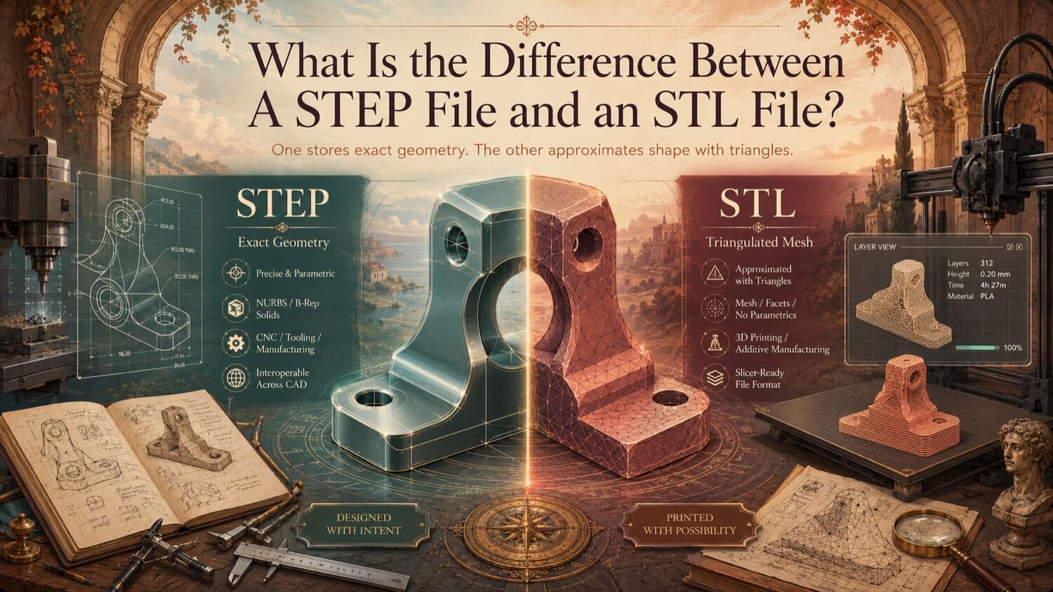
STEP and STL are both 3D file formats, but they represent geometry using fundamentally different mathematical approaches, serve different manufacturing processes, and are not interchangeable. Using the wrong format for a downstream process is one of the most common and costly errors in industrial digitization workflows. Understanding the distinction precisely is essential for every procurement manager, CNC programmer, and additive manufacturing engineer.
How GDS Can Help
Most physical-to-digital projects touch more than one discipline. GDS can support the workflow from field capture through usable engineering deliverables with 3D laser scanning, 3D modeling, reverse engineering, and consulting.
GDS lists coverage across major metropolitan areas including Houston, Dallas, San Antonio, Austin, Los Angeles, San Diego, San Jose, Long Beach, Fort Worth, Irvine, Riverside, New Orleans, Baton Rouge, Shreveport, Las Vegas, and Beverly Hills. See the current GDS locations page for posted service areas.
Scope note: Specific tolerances, certification requirements, deliverables, schedules, reports, site control, and acceptance criteria should be defined in the quote, proposal, or statement of work for the individual project.
Two Completely Different Mathematical Approaches
STEP (.step / .stp) stores geometry using Boundary Representation (B-Rep) mathematics. Every surface in a STEP file is described by an exact analytical equation: planes are defined by a point and a normal vector; cylinders are defined by a central axis and a radius; freeform surfaces are defined by NURBS equations. The geometry is mathematically perfect, there is no approximation, no resolution limit, and no loss of precision when zooming in or generating toolpaths.
STL (.stl) stores geometry using tessellation: the entire outer surface of the object is approximated by a collection of flat triangular faces. A smooth cylindrical bore becomes a polygon approximating a cylinder. The quality of the approximation improves as more triangles are added, but it remains an approximation at every resolution level.
Geometry Precision: Exact vs. Approximate
| Property | STEP (B-Rep) | STL (Mesh) |
|---|---|---|
| Curved surfaces | Analytically exact | Faceted approximation |
| Precision at any zoom | Infinite | Resolution-limited |
| Chord deviation | Zero | Controlled by export settings |
| Internal geometry | Fully captured | Outer surface only |
| Thread geometry | Precisely defined | Cannot be represented |
The practical consequence: a 50 mm diameter bore in a STEP file is a mathematically perfect cylinder with an exact radius of 25.000 mm. The same bore in an STL file is a polygon with a diameter that varies slightly depending on the triangle count, an approximation that introduces measurable dimensional error into every CNC toolpath calculated from it.
Editability: Parametric vs. Locked
A STEP file is a fully editable parametric solid in any receiving CAD environment. An engineer can open a STEP in SolidWorks, Fusion 360, or CATIA, select a face, and modify a dimension, adjusting a bore diameter, extending a wall, or mirroring a feature, without rebuilding the model from scratch.
An STL file is, for practical purposes, locked geometry. While it is theoretically possible to modify an STL file using mesh editing tools (scaling, boolean operations, vertex manipulation), any attempt to change a specific dimension, adjusting a bore from 50 mm to 52 mm, for example, requires manual mesh surgery that introduces non-manifold errors and is far more time-consuming than simply modifying the original STEP feature.
For any project where design modification may be required in the future, STEP is the correct format. STL is appropriate only for final, frozen geometry destined for additive manufacturing.
Manufacturing Compatibility
CNC Machining , Use STEP
CNC Computer-Aided Manufacturing (CAM) software generates cutting paths by evaluating the mathematical surfaces of a solid model. When fed a STEP file, the CAM system computes smooth, continuous cutting paths across exact cylindrical bores, planar faces, and freeform profiles, producing excellent surface finishes and precise dimensional results.
When fed an STL mesh, the CAM system interprets each flat triangle as a distinct machining face. The cutting tool attempts to follow the faceted surface step by step, producing: - Chatter and vibration at each triangle boundary - Accelerated tool wear - Rough, faceted surface finishes - Dimensional errors proportional to triangle size
Always use STEP (or Parasolid .x_t) for CNC machining. Never use STL.
3D Printing , Use STL or 3MF
Additive manufacturing slicing software requires tessellated mesh geometry to calculate layer-by-layer material deposition. STEP geometry must be tessellated (converted to a mesh) before a slicer can process it. Most slicers accept STL natively, and the modern 3MF format is preferred for professional industrial printers because it includes explicit units, material settings, and watertight geometry enforcement that STL lacks.
Use STL or 3MF for 3D printing. STEP files cannot be directly sliced.
File Size and Data Density
For simple geometric parts, STEP files are typically more compact than high-resolution STL files because B-Rep geometry stores a cylinder as a single mathematical expression rather than thousands of triangles. For complex organic geometry (terrain, organic sculptures, medical implants), high-polygon-count STL files may be larger than equivalent STEP files.
Quick Decision Guide
| Manufacturing Process | Required Format | Never Use |
|---|---|---|
| CNC milling / turning | STEP (.step) or Parasolid (.x_t) | STL |
| 3D printing (FDM, SLA, SLS) | STL (.stl) or 3MF (.3mf) | STEP directly |
| Injection molding tooling | STEP (.step) | STL |
| FEA structural simulation | STEP (.step) | STL |
| Deviation inspection | Both (STEP as nominal; STL as scan mesh) | N/A |
| Engineering drawing generation | STEP (.step) or native CAD | STL |
Quick Facts
Continue Reading
The next best article depends on where you are in the project. These suggested reads connect this topic to the next practical decision your team is likely to face.
FAQ
Can I convert an STL file to a STEP file automatically?
Automated converters exist but produce poor-quality, faceted solids unsuitable for CNC machining. Converting an STL to a usable STEP file requires a skilled engineer to reverse-engineer new parametric geometry over the mesh, a manual process that GDS performs as part of its reverse engineering service.
My CNC shop is asking for a STEP file. Can I send an STL instead?
No. CNC CAM software requires the exact analytical surface definitions that only B-Rep formats (STEP, Parasolid) provide. Sending an STL will result in faceted toolpaths, poor surface finish, and dimensional errors. GDS can convert your physical part or existing mesh directly to a verified STEP AP242 file ready for CNC programming.
What is the best format for both CNC and 3D printing of the same part?
Maintain the master in STEP format for CNC machining and design modifications. Export a high-resolution STL or 3MF from the STEP file for 3D printing. Never maintain STL as the master file, design changes cannot be made cleanly in mesh format.
Need Both a STEP and an STL from the Same Physical Part?
GDS delivers STEP AP242 for CNC machining and a watertight STL or 3MF for 3D printing , from any physical object, verified by CAV deviation heatmap.