

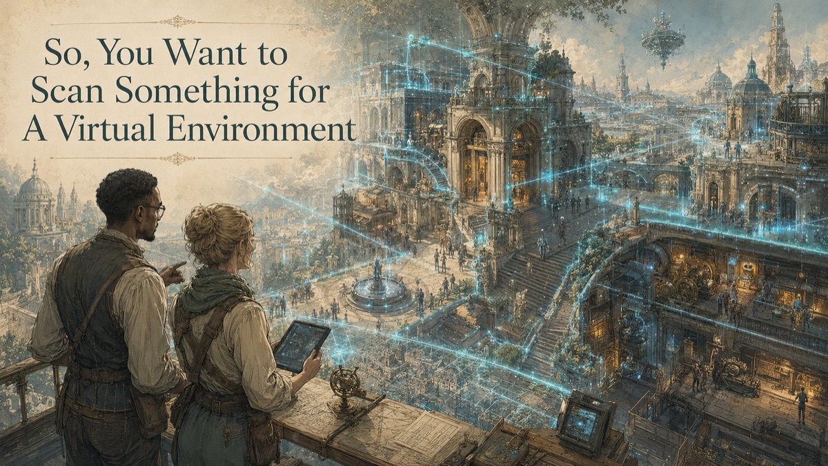
A client asks for a virtual environment, not just a scanned object. Users may walk through rooms, look around corners, inspect equipment, view distant backgrounds, or move from inside to outside. If the scan only captures a route, the world breaks at the first unplanned sightline. If the data is too heavy, the environment cannot stream or run smoothly.
This is why GDS treats scanning as a decision-support workflow, not just a technical field activity. The question is not simply, "Can we scan it?" The more useful question is, "What decision must the data support, and what evidence will make that decision safer?"
Key Takeaway
Building a virtual environment from scans requires a world specification, not just a capture request. Define boundary, coordinates, platform, navigation, interaction, lighting, change state, and performance budget before capture.
The Virtual Environment Problem: Worlds Need Continuity
A virtual environment must support spatial continuity across many objects and viewpoints. Coordinate drift, inconsistent scale, missing transitions, uncontrolled polygon density, and unclear reconstruction can undermine the entire scene. The capture and production plan should identify what is measured, what is simplified, what is reconstructed, and what is intentionally excluded.
The strongest projects separate what is known, what is measured, what is modeled, and what still requires judgment. That protects the client and the service provider because the deliverable becomes evidence with context, not an implied guarantee beyond the approved scope.
What the Scan or Data Package Should Resolve
Reality capture provides the geometric baseline. Terrestrial scanning may establish large spatial context; close-range scanning may document hero assets; photography may support textures. The production pipeline then segments the master, builds derivatives, fills approved gaps, assigns materials, creates collision and navigation, and validates runtime behavior.
A good article page should help the reader choose the right next step. For some projects, that may be a broad spatial baseline. For others, it may be a focused interface scan, a lightweight model, a textured asset, a deviation report, or a consulting engagement before any field capture begins.
The Eight-Phase Scan-to-Environment Workflow
Phase 1 - Define the world and use
Confirm users, routes, camera positions, platform, interaction, reliability expectations, and whether the world is measured, cleaned, historic, or design-intent.
Phase 2 - Establish coordinate control
Set units, origin, axes, elevation, local transformations, and geospatial references where applicable.
Phase 3 - Plan zone-based capture
Allocate coverage, resolution, imagery, and access by visual and functional importance.
Phase 4 - Capture and register
Build a unified point cloud with documented control, site state, gaps, and limitations.
Phase 5 - Preserve and segment the master
Divide the environment into logical spatial zones, assets, textures, materials, and production packages.
Phase 6 - Create derivatives
Generate meshes, CAD references, textures, levels of detail, proxies, and collision surfaces.
Phase 7 - Assemble the world
Apply naming, hierarchy, pivots, materials, streaming boundaries, lighting, and scene organization.
Phase 8 - Validate runtime behavior
Test scale, seams, transitions, navigation, performance, collisions, and missing-view conditions.
Deliverable Strategy
| Deliverable Type | When It Helps | Key Control |
|---|---|---|
| Registered point cloud | Preserves measured visible conditions as source evidence | Capture date, coordinate basis, coverage, and exclusions |
| Mesh or surface asset | Supports visualization, VR, VFX, reproduction, or measured surface review | Repair status, density, texture, scale, and intended use |
| CAD / STEP / IGES | Supports engineering exchange, reverse modeling, interfaces, and downstream design | Modeled-versus-measured status and design-intent assumptions |
| Drawings / exhibits / reports | Supports stakeholder review, procurement, QA, or decision records | Revision, units, review authority, and limitations |
Table accessibility note: The header row defines each deliverable, its best-use case, and the control required before relying on it.
Use Cases
- Real-location digital sets and previsualization
- Interactive facilities and remote site reviews
- Cultural, tourism, education, and exhibition worlds
- Persistent baselines for digital twin or training development
Risks and Misconceptions
Scanning the route does not capture the world
Users can look beyond the intended path. Capture should account for sightlines, transitions, reflections, windows, and reachable areas.
Georeferenced data may need a local shift
Large coordinate values can create precision problems in real-time engines. Any shift should be controlled and documented.
A single mesh is rarely easier long term
Monolithic geometry is difficult to stream, update, cull, texture, and assign. Segmentation should follow spatial and runtime logic.
Reconstruction is not measurement
Filled or inferred areas may be acceptable for production, but they should not be confused with captured geometry.
Virtual Environment Zone Planner
Select the zones that users must see, enter, or interact with. The planner helps distinguish capture priority from background context.
Quick Facts
Continue Reading
The next best article depends on where you are in the project. These suggested reads connect this topic to the next practical decision your team is likely to face.
Frequently Asked Questions
How much surrounding context should be scanned?
Capture every approved visible or reachable area plus buffer geometry needed for transitions, lighting, reflections, and user sightlines.
Can GDS combine terrestrial and close-range scans?
Yes, when datasets can be aligned through suitable control or common geometry, with the method and limitations documented.
Should the environment use survey or local coordinates?
Survey coordinates support integration; local coordinates may improve real-time stability. Many projects preserve both through a controlled transformation.
Can the environment be updated later?
Yes. Modular segmentation, stable coordinates, source preservation, and revision control make targeted updates more practical.
Connect this article to the right GDS workflow
Most physical-to-digital projects touch more than one service. GDS can help determine whether the right starting point is 3D laser scanning, 3D modeling, reverse engineering, or consulting before scope, pricing, schedule, and deliverables are finalized.
GDS supports projects nationwide. Examples from the current locations page include Los Angeles, Long Beach, Irvine, and Riverside.
Ready to Start?
Tell GDS about your asset, your goals, and your deliverable needs. GDS can scope the right scanning, modeling, and reporting for your project.